Diagnostic trouble code C1242 Land Cruiser
DESCRIPTION
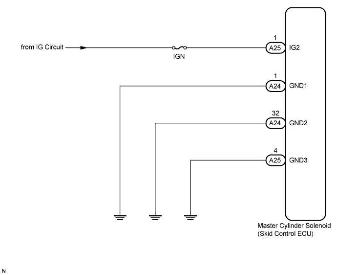
WIRING DIAGRAM
INSPECTION PROCEDURE
INSPECT BATTERY
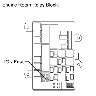
INSPECT IGN FUSE
INSPECT SKID CONTROL ECU (IG2 TERMINAL)
INSPECT SKID CONTROL ECU (GND TERMINAL)
RECONFIRM DTC
DTC C1242/42 IG2 Power Source Circuit
Description
If there is a problem with the master cylinder solenoid (skid control ECU) power supply circuit, the skid control ECU stores DTCs and prohibits operation under the fail-safe function.
If the voltage supplied to the IG2 terminal is within the DTC detection range due to malfunctions in components such as the battery and alternator circuit, this DTC is stored.
| DTC Code |
DTC Detection Condition |
Trouble Area |
| C1242/42 |
The vehicle speed is 3 km/h (1.9 mph) or more and the voltage of the ECU IG2 terminal remains below 6.5 V for more than 7 seconds. |
- Battery
- IGN fuse
- Charging system
- Harness or connector
- Master cylinder solenoid (Skid control ECU)
|
Wiring diagram
Inspection procedure
NOTICE:
When replacing the master cylinder solenoid, perform zero point calibration .
-
Check the battery voltage.
Standard voltage:
11 to 14 V
Result
| Result |
Proceed to |
| OK |
A |
| NG |
1GR-FE |
B |
| 2UZ-FE |
C |
| 1VD-FTV |
D |
|
|
| GO TO CHARGING SYSTEM (ON-VEHICLE INSPECTION) |
|
| |
|
|
| GO TO CHARGING SYSTEM (ON-VEHICLE INSPECTION) |
|
| |
|
|
| GO TO CHARGING SYSTEM (ON-VEHICLE INSPECTION) |
|
| |
-
Remove the IGN fuse from the engine room relay block.
-
Measure the resistance according to the value(s) in the table below.
Standard Resistance:
| Tester Connection |
Condition |
Specified Condition |
| IGN fuse |
Always |
Below 1 ? |
| 3.INSPECT SKID CONTROL ECU (IG2 TERMINAL) |
-
Install the IGN fuse.
-
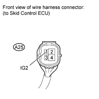
Disconnect the A25 skid control ECU connector.
-
Measure the voltage according to the value(s) in the table below.
Standard Voltage:
| Tester Connection |
Switch Condition |
Specified Condition |
| A25-1 (IG2) - Body ground |
Ignition switch ON |
11 to 14 V |
|
|
| REPAIR OR REPLACE HARNESS OR CONNECTOR |
|
| |
| 4.INSPECT SKID CONTROL ECU (GND TERMINAL) |
-
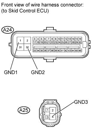
Disconnect the A24 and A25 skid control ECU connectors.
-
Measure the resistance according to the value(s) in the table below.
Standard Resistance:
| Tester Connection |
Condition |
Specified Condition |
| A24-1 (GND1) - Body ground |
Always |
Below 1 ? |
| A24-32 (GND2) - Body ground |
Always |
Below 1 ? |
| A25-4 (GND3) - Body ground |
Always |
Below 1 ? |
|
|
| REPAIR OR REPLACE HARNESS OR CONNECTOR |
|
| |
-
Clear the DTC .
-
Check if the same DTC is output .
HINT:
Reinstall the sensors, connectors, etc. and restore the previous vehicle conditions before rechecking for DTCs.
Result
| Result |
Proceed to |
| DTC is not output |
A |
| DTC is output |
LHD |
B |
| RHD |
C |
|
|
| REPLACE MASTER CYLINDER SOLENOID |
|
| |
|
|
| REPLACE MASTER CYLINDER SOLENOID |
|
| |
| A |
|
| |
|
| USE SIMULATION METHOD TO CHECK |
|