ECD system
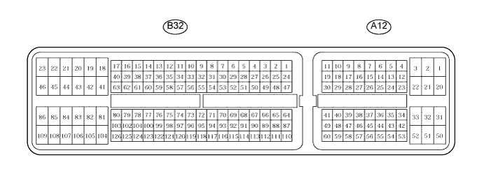
Terminals of ECM
-
Measure the voltage of the ECM connector.
HINT:
Each ECM terminal's standard voltage is shown in the table below.
In the table, first follow the information in "Condition". Look at "Symbols (Terminal No.)" for the terminals to be inspected. The standard voltage between the terminals is shown in "Specified Condition".
Use the illustration above as a reference for the ECM terminals.
Symbols (Terminal No.) Wiring Color Terminal Description Condition Specified Condition BATT (A12-2) - E1 (B32-109) W - BR Battery (for measuring the battery voltage and for the ECM memory) Always 9 to 14 V IGSW (A12-25) - E1 (B32-109) B - BR Ignition switch Ignition switch on (IG) 9 to 14 V +B (A12-1) - E1 (B32-109) B - BR Power source of ECM Ignition switch on (IG) 9 to 14 V MREL (A12-45) - E1 (B32-109) O - BR EFI MAIN relay Ignition switch on (IG) 9 to 14 V MREL (A12-45) - E1 (B32-109) O - BR EFI MAIN relay 2 seconds elapsed after ignition switch off 0 to 1.5 V IREL (A12-44) - E1 (B32-109) R - BR EDU relay ignition switch off 9 to 14 V IREL (A12-44) - E1 (B32-109) R - BR EDU relay Idling 0 to 1.5 V GREL (B32-56) - E1 (B32-109) L - BR Glow plug relay Cranking 9 to 14 V GREL (B32-56) - E1 (B32-109) L - BR Glow plug relay Idling (Engine start after 10 minutes or more) 0 to 1.5 V VPA (A12-53) - EPA (A12-57) W - Y Accelerator pedal position sensor (for engine control) Ignition switch on (IG), accelerator pedal fully released 0.5 to 1.1 V VPA (A12-53) - EPA (A12-57) W - Y Accelerator pedal position sensor (for engine control) Ignition switch on (IG), accelerator pedal fully depressed 3.0 to 4.6 V VPA2 (A12-54) - EPA2 (A12-58) R - O Accelerator pedal position sensor (for sensor malfunction detection) Ignition switch on (IG), accelerator pedal fully released 0.9 to 2.3 V VPA2 (A12-54) - EPA2 (A12-58) R - O Accelerator pedal position sensor (for sensor malfunction detection) Ignition switch on (IG), accelerator pedal fully depressed 3.4 to 5.0 V VCPA (A12-55) - EPA (A12-57) B - Y Power source of accelerator pedal position sensor (for VPA1) Ignition switch on (IG) 4.5 to 5.5 V VCP2 (A12-56) - EPA2 (A12-58) L - O Power source of accelerator pedal position sensor (for VPA2) Ignition switch on (IG) 4.5 to 5.5 V STAR (B32-53)* - E1 (B32-109) W - BR ST relay control Cranking 9 to 14 V STA (A12-43) - E1 (B32-109) LG - BR Starter signal Cranking 6.0 V or more INJF (B32-51) - E1 (B32-109) P - BR EDU Idling Pulse generation
(see waveform 3)#1 (B32-50) - E1 (B32-109)
#2 (B32-49) - E1 (B32-109)
#3 (B32-48) - E1 (B32-109)
#4 (B32-47) - E1 (B32-109)GR - BR
G - BR
LG - BR
L - BRInjector Idling Pulse generation
(see waveform 2)PRD (B32-52) - E1 (B32-109) B - BR Pressure relief valve drive signal Ignition switch off 4 to 5.5 V IDLO (B32-62) - E1 (B32-109) Y - BR EDU Idling 4 to 5.5 V NE+ (B32-78) - NE- (B32-77) B - W Crankshaft position sensor Idling Pulse generation
(see waveform 4)G+ (B32-80) - G- (B32-79) R - G Camshaft position sensor Idling Pulse generation
(see waveform 4)STP (A12-35) - E1 (B32-109) L - BR Normally open switch Ignition switch on (IG), brake pedal depressed 7.5 to 14 V STP (A12-35) - E1 (B32-109) L - BR Normally open switch Ignition switch on (IG), brake pedal released 0 to 1.5 V ST1- (A12-34) - E1 (B32-109) GR - BR Normally closed switch Ignition switch on (IG), brake pedal depressed 0 to 1.5 V ST1- (A12-34) - E1 (B32-109) GR - BR Normally closed switch Ignition switch on (IG), brake pedal released 7.5 to 14 V TC (A12-26) - E1 (B32-109) G - BR Terminal TC of DLC3 Ignition switch on (IG) 9 to 14 V W (A12-12) - E1 (B32-109) R - BR MIL MIL illuminated 0 to 3 V W (A12-12) - E1 (B32-109) R - BR MIL MIL not illuminated 9 to 14 V SPD (A12-14) - E1 (B32-109) V - BR Speed signal from combination meter Ignition switch on (IG), drive wheels are rotating slowly Pulse generation
(see waveform 7)PIM (B32-117) - EPIM (B32-94) G - BR Manifold absolute pressure sensor Apply negative pressure of 40 kPa (300 mmHg, 11.8 in.Hg) 0.3 to 0.9 V PIM (B32-117) - EPIM (B32-94) G - BR Manifold absolute pressure sensor Same as atmospheric pressure 0.8 to 1.4 V PIM (B32-117) - EPIM (B32-94) G - BR Manifold absolute pressure sensor Apply positive pressure of 69 kPa (518 mmHg, 20.3 in.Hg) 1.6 to 2.2 V TACH (A12-13) - E1 (B32-109) GR - BR Engine speed Idling Pulse generation
(see waveform 8)VCS (B32-68) - E2S (B32-66) R - BR Common rail pressure sensor Ignition switch on (IG) 4.5 to 5.5 V PCR1 (B32-67) - E2M (B32-91) P - BR Common rail pressure sensor (main) Idling 1.8 to 2.1 V PCR2 (B32-114) - E2S (B32-66) W - BR Common rail pressure sensor (sub) Idling 1.2 to 1.5 V ALT (B32-54) - E1 (B32-109) B - BR Generator duty ratio Idling Pulse generation
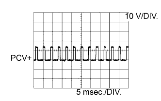
(see waveform 9)PCV+ (B32-42) - PCV- (B32-41) LG - R Suction control valve Idling Pulse generation
(see waveform 1)VN (B32-84) - E1 (B32-109) Y - BR VRV (for VN turbocharger) Ignition switch on (IG) Pulse generation
(see waveform 5)FIV (B32-105) - E1 (B32-109) GR - BR Exhaust fuel addition injector Engine warmed up, idling, every 1 to 2 minutes Pulse generation VLU (B32-119) - EVLU (B32-96) G - BR Throttle position sensor Ignition switch on (IG), throttle valve fully opened 2.8 to 3.8 V LUSL (B32-86) - E1 (B32-109) V - BR Throttle valve duty signal Engine warmed up, engine racing Pulse generation
(see waveform 6)EGLS (B32-118) - EEGL (B32-95) GR - BR EGR valve position sensor Ignition switch on (IG) 0.6 to 1.4 V EGRS (B32-85) - E1 (B32-109) W - BR EGR Engine warmed up, idling Pulse generation
(see waveform 10)THCO (B32-121) - ETCO (B32-98) P - BR Exhaust gas temperature sensor Engine warmed up, idling 4.6 to 4.9 V THCI (B32-122) - ETCI (B32-99) L - BR Exhaust gas temperature sensor Engine warmed up, idling 4.6 to 4.9 V THIA (B32-113) - ETHI (B32-90) Y - BR Intake air temperature sensor (Intake manifold) Idling, intake air temperature at 0 to 80°C (32 to 176°F) 0.5 to 3.4 V THF (B32-112) - ETHF (B32-89) GR - BR Fuel temperature sensor Ignition switch on (IG) 0.5 to 3.4 V THW (B32-111) - ETHW (B32-88) B - BR ECT sensor Idling, engine coolant temperature at 60 to 120°C (140 to 248°F) 0.2 to 1.0 V PEX (B32-120) - EPEX (B32-97) P - BR Differential pressure sensor Ignition switch on (IG) 0.4 to 4.8 V HAF2 (B32-104) - E05 (B32-46) L - W-B A/F sensor heater Ignition switch on (IG) 9 to 14 V AF2+ (B32-103) - E1 (B32-109) L - BR A/F sensor Ignition switch on (IG) 2.0 to 2.5 V AF2- (B32-126) - E1 (B32-109) Y - BR A/F sensor Ignition switch on (IG) 2.0 to 2.5 V VG (B32-65) - EVG (B32-64) LG - W MAF meter power source Engine idling 0.5 to 3.4 V THA (B32-110) - ETHA (B32-87) L - BR IAT sensor Idling, intake air temperature at 0 to 80°C (32 to 176°F) 0.5 to 3.4 V FANL (A12-22) - E1 (B32-109) R - BR FAN NO. 3 relay Ignition switch on (IG) 9 to 14 V FANL (A12-22) - E1 (B32-109) R - BR FAN NO. 3 relay Idling with A/C ON
or
High engine coolant temperatureBelow 1.5 V FANH (A12-21) - E1 (B32-109) W - BR FAN NO. 1, 2 relay Idling with high engine coolant temperature Below 1.5 V ACCR (A12-24)* - E1 (B32-109) LG - BR Accessory power cut signal Ignition switch on (IG) > Cranking Below 1.5 V STSW (A12-9)* - E1 (B32-109) R - BR Engine cranking required signal Ignition switch on (IG) > Cranking Below 1 V > 9 to 14 V momentary VCIB (B32-70) - EIB (B32-93) R - BR Battery current sensor Ignition switch on (IG) 4.5 to 5.0 V IB (B32-116) - EIB (B32-93) B - BR Battery current sensor Ignition switch on (IG) 0.5 to 4.5 V THB (B32-115) - EIB (B32-93) LG - BR Battery current sensor Ignition switch on (IG) 0.5 to 4.5 V CANH (A12-38) - E1 (B32-109) Y - BR CAN communication line Ignition switch on (IG) Pulse generation
(see waveform 11)CANL (A12-46) - E1 (B32-109) W - BR CAN communication line Ignition switch on (IG) Pulse generation
(see waveform 12)HINT:
*: w/ Entry and start system.
-
Using an oscilloscope, check the waveform 1.
Waveform 1:
Suction control valve signal
Item Content Symbols (Terminal No.) PCV+ (B32-42) - PCV- (B32-41) Tool Setting 10 V/DIV., 5 msec./DIV. Condition Idling or cranking with warm engine HINT:
The waveform varies depending on the suction control valve operation.
-
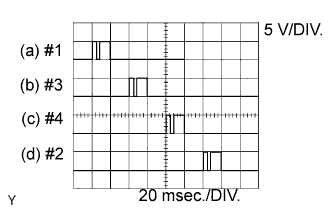
Using an oscilloscope, check the waveform 2.
Waveform 2:
No. 1 injector injection signal
No. 2 injector injection signal
No. 3 injector injection signal
No. 4 injector injection signalItem Content Symbols (Terminal No.) (a) #1 (B32-50) - E1 (B32-109)
(b) #3 (B32-49) - E1 (B32-109)
(c) #4 (B32-48) - E1 (B32-109)
(d) #2 (B32-47) - E1 (B32-109)Tool Setting 5 V/DIV., 20 msec./DIV. Condition Idling with warm engine HINT:
The waveform varies depending on the injector injection.
-
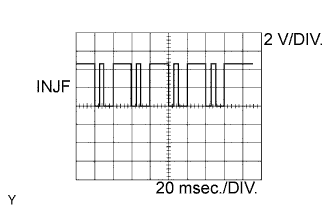
Using an oscilloscope, check the waveform 3.
Waveform 3:
Injector injection confirmation signal
Item Content Symbols (Terminal No.) INJF (B32-51) - E1 (B32-109) Tool Setting 2 V/DIV., 20 msec./DIV. Condition Idling with warm engine HINT:
The waveform varies depending on the injector injection.
-
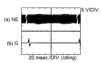
Using an oscilloscope, check the waveform 4.
Waveform 4:
Crankshaft position sensor signal
Camshaft position sensor signal
Item Content Symbols (Terminal No.) (a) NE+ (B32-78) - NE- (B32-77)
(b) G+ (B32-80) - G- (B32-79)Tool Setting 5 V/DIV., 20 msec./DIV. Condition Idling with warm engine HINT:
The waveform varies depending on the engine revolution.
-
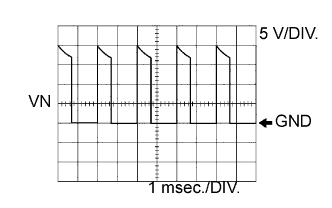
Using an oscilloscope, check the waveform 5.
Waveform 5:
VRV for turbocharger control signal
Item Content Symbols (Terminal No.) VN (B32-84) - E1 (B32-109) Tool Setting 5 V/DIV., 1 msec./DIV. Condition Idling with warm engine HINT:
The waveform changes depending on the electric vacuum regulating valve for turbocharger operation.
-
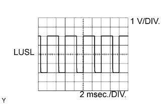
Using an oscilloscope, check the waveform 6.
Waveform 6:
Diesel throttle signal
Item Content Symbols (Terminal No.) LUSL (B32-86) - E1 (B32-109) Tool Setting 1 V/DIV., 2 msec./DIV. Condition Warm engine with engine racing HINT:
The waveform varies depending on the throttle valve operation.
-
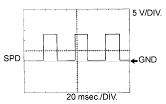
Using an oscilloscope, check the waveform 7.
Waveform 7:
Vehicle speed signal
Item Content Symbols (Terminal No.) SPD (A12-14) - E1 (B32-109) Tool Setting 5 V/DIV., 20 msec./DIV. Condition Driving the vehicle HINT:
The wavelength becomes shorter as the vehicle speed increases.
-
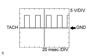
Using an oscilloscope, check the waveform 8.
Waveform 8:
Engine speed signal
Item Content Symbols (Terminal No.) TACH (A12-13) - E1 (B32-109) Tool Setting 5 V/DIV., 20 msec./DIV. Condition Idling with warm engine HINT:
The wavelength becomes shorter as the engine speed increases.
-
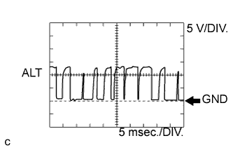
Using an oscilloscope, check the waveform 9.
Waveform 9:
Generator signal
Item Content Symbols (Terminal No.) ALT (B32-54) - E1 (B32-109) Tool Setting 5 V/DIV., 5 msec./DIV. Condition Idling -
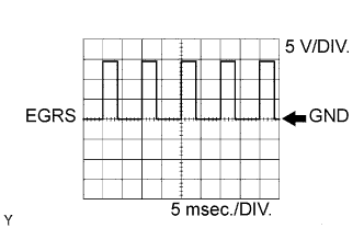
Using an oscilloscope, check the waveform 10.
Waveform 10:
EGR position sensor signal
Item Content Symbols (Terminal No.) EGRS (B32-85) - EEGL (B32-95) Tool Setting 5 V/DIV., 5 msec./DIV. Condition Idling -
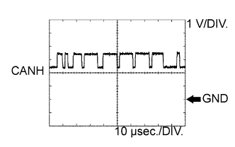
Using an oscilloscope, check the waveform 11.
Waveform 11:
CAN communication signal
Item Content Symbols (Terminal No.) CANH (A12-38) - E1 (B32-109) Tool Setting 1 V/DIV., 10 ?sec./DIV. Condition Engine stopped and ignition switch on (IG) HINT:
The waveform varies depending on the CAN communication signal.
-
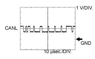
Using an oscilloscope, check the waveform 12.
Waveform 12:
CAN communication signal
Item Content Symbols (Terminal No.) CANL (A12-46) - E1 (B32-109) Tool Setting 1 V/DIV., 10 ?sec./DIV. Condition Engine stopped and ignition switch on (IG) HINT:
The waveform varies depending on the CAN communication signal.