DTC P2121 Throttle / Pedal Position Sensor / Switch "D" Circuit Range / Performance
HINT:
- This is the repair procedure for the accelerator pedal position sensor.
- This electrical throttle system does not use a throttle cable.
- This accelerator pedal position sensor is a non-contact type.
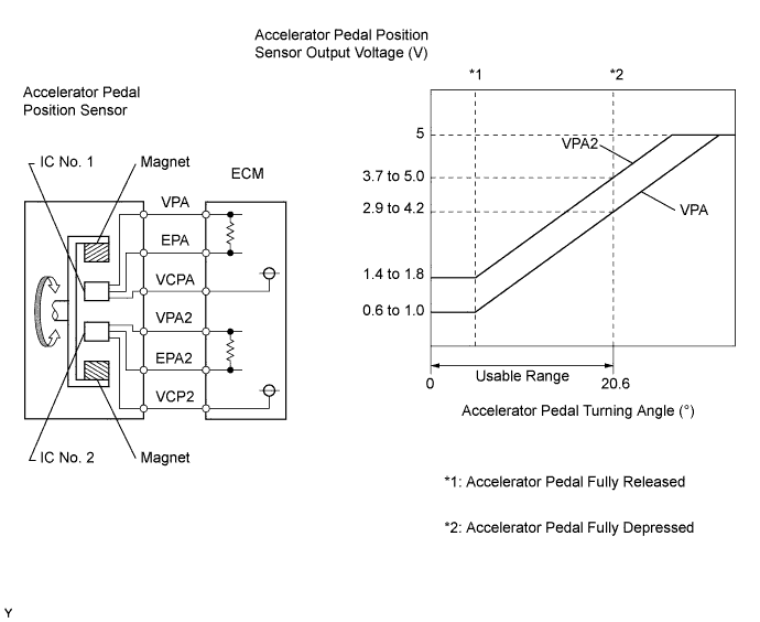
The accelerator pedal position sensor is mounted on the accelerator pedal and detects the opening angle of the accelerator pedal. Since this sensor is electronically controlled with Hall-effect elements, accurate control and reliability can be obtained. It has 2 sensors to detect both the accelerator position and a malfunction of the accelerator position sensor.
In the accelerator pedal position sensor, the voltage applied to pedal terminals VPA and VPA2 of the ECM changes between 0 V and 5 V in proportion to the opening angle of the accelerator pedal. The VPA is a signal to indicate the actual accelerator pedal opening angle which is used for the engine control, and the VPA2 is a signal to indicate the information about the opening angle which is used for detecting malfunctions. The ECM determines the current opening angle of the accelerator pedal using signals from terminals VPA and VPA2, and the ECM controls the throttle motor based on these signals.
Toyota fault code list DTC P2121
| DTC No. | DTC Detection Condition | Trouble Area |
| P2121 | Condition (a) continues for 2 seconds: (a) Difference between VPA1 and VPA2 exceeds the threshold (1 trip detection logic) |
|
Wiring diagram
Inspection procedure
NOTICE:
After replacing the ECM, the new ECM needs registration and initialization.
| 1.READ VALUE OF ACCELERATOR PEDAL POSITION SENSOR |
-
Connect the intelligent tester to the DLC3.
-
Turn the ignition switch on (IG) and turn the tester ON.
-
Enter the following menus: Powertrain / Engine and ECT / Data List / Accel Position 1 and Accel Position 2.
-
Read the values.
Standard voltage:
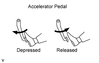
Accelerator Pedal Accel Position 1 Accel Position 2 Released 0.6 to 1.0 V 1.4 to 1.8 V Depressed 3.4 to 3.8 V 4.2 to 4.6 V
|
|
||||
| NG | |
| 2.CHECK WIRE HARNESS (ACCELERATOR PEDAL POSITION SENSOR - ECM) |
-
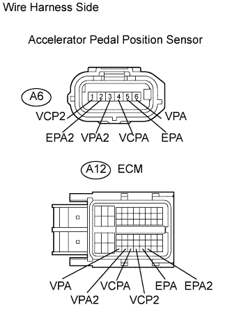
Disconnect the A6 accelerator pedal position sensor connector.
-
Disconnect the A12 ECM connector.
-
Measure the resistance of the wire harness side connectors.
| Tester Connection | Specified Condition |
| A6-1 (VCP2) - A12-56 (VCP2) | Below 1 ? |
| A6-2 (EPA2) - A12-58 (EPA2) | Below 1 ? |
| A6-3 (VPA2) - A12-54 (VPA2) | Below 1 ? |
| A6-4 (VCPA) - A12-55 (VCPA) | Below 1 ? |
| A6-5 (EPA) - A12-57 (EPA) | Below 1 ? |
| A6-6 (VPA) - A12-53 (VPA) | Below 1 ? |
| A6-1 (VCP2) or A12-56 (VCP2) - Body ground | 10 k? or higher |
| A6-2 (EPA2) or A12-58 (EPA2) - Body ground | 10 k? or higher |
| A6-3 (VPA2) or A12-54 (VPA2) - Body ground | 10 k? or higher |
| A6-4 (VCPA) or A12-55 (VCPA) - Body ground | 10 k? or higher |
| A6-5 (EPA) or A12-57 (EPA) - Body ground | 10 k? or higher |
| A6-6 (VPA) or A12-53 (VPA) - Body ground | 10 k? or higher |
-
Reconnect the accelerator pedal position sensor connector.
-
Reconnect the ECM connector.
|
|
||||
| OK | |
|