DTC P2002 Particulate Trap Efficiency Below Threshold (Bank1)
Description
HINT:
- For more information on the DPNR*1 catalytic converter and TOYOTA D-CAT*2, refer to the following procedures.
- If P2002 is present, refer to the DTC table for TOYOTA D-CAT.
*1: Diesel Particulate-NOx Reduction system.
*2: Diesel Clean Advanced Technology.
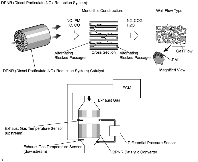
The DPNR catalyst has an ability to reduce nitrogen oxides (NOx), particulate matter (PM), hydrocarbons (HC) and carbon monoxides (CO). The DPNR catalyst is a monolithic type catalyst. Alternating passages in the catalyst have either their inlet or outlet blocked. This forces the exhaust gasses to flow through the walls of the passages (see illustration above). The passages are coated with a NOx absorptive deduction type catalyst. Due to the flow of the exhaust gasses through micro-cavities in the passage walls, it is called a "wall flow" type converter.
Toyota fault code list DTC P2002
| DTC No. | DTC Detection Condition | Trouble Area |
| P2002 | Condition (a) or (b) is met (1 trip detection logic): (a) Differential pressure exceeds a standard level for more than 10 seconds (b) Exhaust gas temperature does not raise during DPNR catalyst regeneration The DPNR catalyst thermal deterioration data exceeds the threshold. |
|
Monitor description
In order to detect abnormality in the DPNR*3 catalytic converter, the ECM monitors an exhaust gas temperature as well as a differential pressure of the exhaust gas. For monitoring the differential pressure, the ECM compares the upstream and downstream pressure of the DPNR catalytic converter. If the difference between the pressure is large, the ECM determines that the DPNR has become contaminated or is deteriorated, and illuminates the MIL.
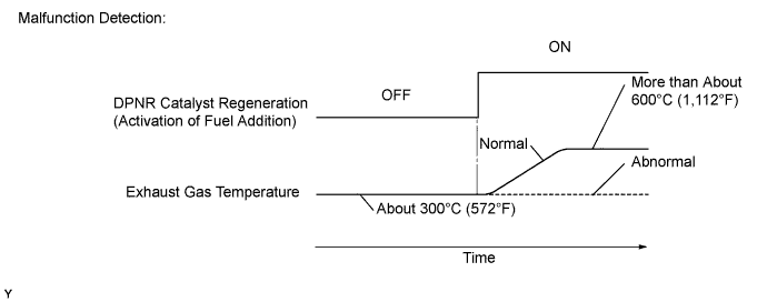
Furthermore, the ECM monitors an increase in the exhaust gas temperature while the exhaust fuel addition injector adds fuel under DPNR catalyst regeneration. The exhaust gas temperature during the DPNR catalyst regeneration normally rises from approximately 300°C (572°F) to approximately 600°C (1,112°F) or higher. If the temperature does not rise even if a certain period of time has elapsed, the ECM interprets this as malfunction of the DPNR and illuminates the MIL.
*3: Diesel Particulate-NOx Reduction system.
Inspection procedure
NOTICE:
After replacing the DPNR catalyst, clear the thermal deterioration data stored in ECM.
HINT:
If a difference in pressure (DPNR DIFF PRESS) does not occur as engine speed is increased, the DPNR catalytic converter may be malfunctioning.
| 1.CHECK CATALYST RECORD OF DPNR THERMAL DETERIORATION |
-
Connect the intelligent tester to the DLC3.
-
Turn the ignition switch on (IG) and turn the tester ON.
-
Enter the following menus: Powertrain / Engine and ECT / Data List / DPNR Catalyst Deteriorate.
OK:
Normal
|
|
||||
| OK | |
| 2.CHECK OTHER DTC OUTPUT (IN ADDITION TO DTC 2002) |
-
Connect the intelligent tester to the DLC3.
-
Turn the ignition switch on (IG) and turn the tester ON.
-
Enter the following menus: Powertrain / Engine and ECT / DTC.
-
Read DTCs.
Result:
| Display (DTC Output) | Proceed to |
| P2002 | A |
| P2002 and other DTCs | B |
HINT:
If codes other than P2002 are output, perform troubleshooting for those DTCs first.
|
|
||||
| A | |
| 3.READ VALUE OF FREEZE FRAME DATA |
-
Connect the intelligent tester to the DLC3.
-
Turn the ignition switch on (IG) and turn the tester ON.
-
Enter the following menus: Powertrain / Engine and ECT / DTC / FREEZE FRAME DATA.
-
Read freeze frame data.
| Item | Data | Proceed to |
| DPNR PM Block | Blocked | A |
| DPNR No Activate | No activate | B |
|
|
||||
| A | |
| 4.CHECK BLOCKAGE OF VACUUM HOSE AND TRANSMITTING PIPE |
CAUTION:
Be careful of being burned by exhaust gases during the following inspection.
-
Disconnect the vacuum hose (both upstream and downstream) on the differential pressure sensor side.
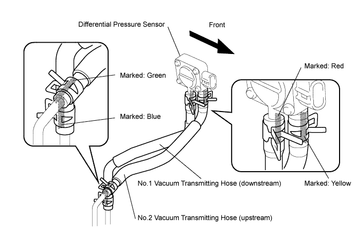
-
Start the engine.
-
Check if there are exhaust gas pulsations from both vacuum hoses while the engine is idling.
|
|
||||
| OK | |
| 5.CHECK FOR EXHAUST GAS LEAKS |
-
Check that there is no exhaust gas leak in the exhaust system components and differential pressure sensor vacuum hoses.
|
|
||||
| OK | |
| 6.READ VALUE OF DIFFERENTIAL PRESSURE |
-
Connect the intelligent tester to the DLC3.
-
Turn the ignition switch on (IG) and turn the tester ON.
-
Start the engine.
-
Enter the following menus: Powertrain / Engine and ECT / Data List / Differential Pressure FB and MAF.
-
Check that differential pressure.
| Engine Speed (Vehicle is stop) | Differential Pressure (kPa) | Proceed to |
| 3,000 rpm (No engine load) | Less than MAF rate (mass air flow rate) x 0.31 | A |
| 3,000 rpm (No engine load) | More than MAF rate (mass air flow rate) x 0.31 | B |
HINT:
- If the differential pressure is more than value of the intake air amount (MAF: g/sec.) multiplied by 0.31, DTC P2002 (Particulate Trap Efficiency Below Threshold [Bank 1]) will be present.
- The standards for the differential pressure sensor are as follows:
Reference:
| Condition | Differential Pressure Output | Sensor Condition |
| Ignition switch on (IG) | Approximately 0 kPa | Normal |
| Always | 3 kPa | Open or short circuit |
| 3,000 rpm (No engine load) | Negative output | Incorrect arrangement of hose piping |
|
|
||||
| A | |
| 7.READ VALUE OF EXHAUST GAS TEMPERATURE |
-
Connect the intelligent tester to the DLC3.
-
Turn the ignition switch on (IG) and turn the tester ON.
-
Start the engine.
-
Enter the following menus: Powertrain / Engine and ECT / Data List / Initial Exhaust Temperature (In) and Initial Exhaust Temperature (Out).
-
Check that the exhaust gas temperature is within the specification below.
*: There should be no noise.Reference: Condition Exhaust Gas Temperature Idling after engine warm-up Constant at approximately 50 to 700°C (122 to 1,292°F)*
|
|
||||
| OK | |
| 8.PERFORM ACTIVE TEST BY EXHAUST FUEL ADDITION INJECTOR (ACTIVE THE DPNR REJUVENATE (PM)) |
-
Connect the intelligent tester to the DLC3.
-
Turn the ignition switch on (IG) and turn the tester ON.
-
Drive the vehicle.
-
Enter the following menus: Powertrain / Engine and ECT / Data List / Active the DPNR Rejuvenate (PM).
-
After warming up the engine, drive the vehicle at a constant speed within 50 to 100 km/h (31 to 62 mph) (with smooth throttle operation) for more than 15 minutes.
-
Check that the exhaust gas temperature is after switching the DPNR Rejuvenate (PM) from OFF to ON.
OK:
The exhaust gas temperature increases by 100°C (212°F) or more.
|
|
||||
| NG | |
| 9.READ VALUE OF INJECTOR (INJECTION FEEDBACK VAL AND INJECTION VOLUME) |
-
Select the following menu items in order and read the values.
- Injection Feedback Val #1, #2, #3, and #4
-
Start and run the engine at idle.
Standard value:
Item Engine Speed* Standard Range Description Injection Feedback Val #1 Idling -3.0 to 3.0 mm3 Value of injector fuel injection volume compensates for differences in combustion condition of cylinders - Positive values indicate control which corrects combustion deterioration
- Negative values indicate control which corrects excessive combustion pressure
- If problems exist, "Injection Feedback Val" may deviate from the -3.0 and 3.0 mm3 range
Injection Feedback Val #2 Idling -3.0 to 3.0 mm3 Injection Feedback Val #3 Idling -3.0 to 3.0 mm3 Injection Feedback Val #4 Idling -3.0 to 3.0 mm3 Injection Volume Idling 3.9 to 7.0 mm3 Fuel injection volume value controlled by ECU - Controls NE signal, fuel temperature, engine coolant temperature, intake air temperature, boost pressure, atmospheric pressure, and EGR volume
- If problems exist, "Injection Volume" may be outside the standard range
HINT:
*: The A/C switch and all accessory switches should be OFF, and the engine should be fully warmed up.
|
|
||||
| OK | |
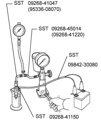
| 10.CHECK EXHAUST FUEL ADDITION INJECTOR (INJECTION VOLUME) |
-
Remove the exhaust fuel addition injector.
-
Using SST, attach the exhaust fuel addition injector to a nozzle tester.
Специальный инструмент (SST):
09268-41047 (95336-08070)
09268-45014 (09268-41220)
09268-41150
-
Apply a pressure of 0.29 MPa (3.0 kgf/cm2, 42 psi) to the nozzle tester.
-
Connect SST (wire) to the exhaust fuel addition injector.
Специальный инструмент (SST):
09842-30080
-
Inspect the injector.
OK:
Condition Result Leave the injector undisturbed for 1 minute with fuel pressurized No leakage from the injector Apply battery voltage to the injector Fuel is emitted from the injector HINT:
- Injection volume after leaving the exhaust fuel addition injector for 10 seconds with the pressurized fuel applied as follows.
Reference:
25 cm3 (1.5 cu.in.)
- The above is a reference value. Your reading may differ from this value depending on the measuring conditions, etc.
- Check that the nozzle of the exhaust fuel addition injector is not clogged.
- Injection volume after leaving the exhaust fuel addition injector for 10 seconds with the pressurized fuel applied as follows.
-
Reinstall the exhaust fuel addition injector.
|
|
||||
| OK | |
| 11.CHECK TURBOCHARGER ACTUATOR |
-
Inspect the actuator.
OK:
The valve has no contamination and it moves smoothly.
|
|
||||
| OK | |
| 12.READ VALUE OF MAF METER |
-
Connect the intelligent tester to the DLC3.
-
Start the engine and warm it up and turn the tester ON.
-
Enter the following menus: Powertrain / Engine and ECT / Data List.
-
Select the following menu item and read the values.
- MAF
Standard value:
| Item | Engine Speed*1 | Standard Range | Description |
| MAF*2, *3 | Ignition switch on (IG) (engine stopped) | 0 g/sec. | Intake air volume detected by mass air flow meter |
| Idling | 2.5 to 5.5 g/sec. | ||
| 3,000 rpm (no engine load) | 49 to 57 g/sec. | ||
| 3,000 rpm (driving with full throttle acceleration) | 124 to 136 g/sec. | ||
| 3,600 rpm (driving with full throttle acceleration) | 151 to 163 g/sec. |
HINT:
*1: The A/C switch and all accessory switches should be OFF with a fully warm engine.
*2: This value is indicated when the ambient temperature is 25°C (77°F), the atmospheric pressure is 101 kPa (758 mmHg, 29.83 in.Hg), and the stable boost pressure is maintained for approximately 10 seconds.
*3: When the mass air flow meter malfunctions, the MAF output may deviate from the standard (referential) range when the engine idles and is accelerated from 3,000 to 4,000 rpm with full throttle acceleration.
|
|
||||
| OK | |
|