DTC P1271 Fuel Regulator Circuit Malfunction (EDU Drive)
DTC P1272 Fuel Pressure Regulator Malfunction
Description
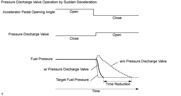
The ECM controls the internal fuel pressure of the common rail by opening and closing the pressure discharge valve. When sudden deceleration occurs, the internal fuel pressure will temporarily become higher than usual and combustion noise may result. Therefore the ECM will open the valve temporarily to discharge the excess pressure inside the common rail. Also, the pressure discharge valve opens when the ignition switch is turned off to allow prompt discharge of the common rail internal pressure.
HINT:
- For more information on the pressure discharge valve and the common rail system, refer to the following procedures.
- For more information on the EDU, refer to the following procedures.
- If P1271 and/or P1272 is present, refer to the DTC chart for the fuel system.
Toyota fault code listDTC P1271 DTC P1272
| DTC No. | DTC Detection Condition | Trouble Area |
| P1271 | Open or short in pressure discharge valve circuit. There is no valve opening confirmation (IJf) signal from EDU to ECM despite the ECM sending valve opening command (PRD) signal after the engine is started. (1 trip detection logic) |
|
| P1272 | Pressure discharge valve closed malfunction. Actual pressure decreasing rate deviates from the simulated pressure decreasing rate after the ignition switch is turned off. (2 trip detection logic) |
|
HINT:
- After confirming DTC P1271 and/or P1272, check the fuel pressure inside the common rail in the "Powertrain / Engine and ECT / Data List / Fuel Press" menu using the intelligent tester.
- P1271: After clearing the DTC, drive the vehicle at 50 km/h (31 mph) with the third gear and then decelerate by releasing the accelerator pedal. Check that P1271 is not present.
- P1272: After clearing the DTC, start and stop the engine twice, and then confirm that P1272 is not present.
| Engine Speed | Fuel Pressure (MPa) |
| Idling | Approximately 37 to 43 |
| 2,500 rpm (No engine load) | Approximately 57 to 63 |
Monitor description
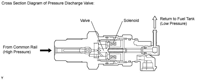
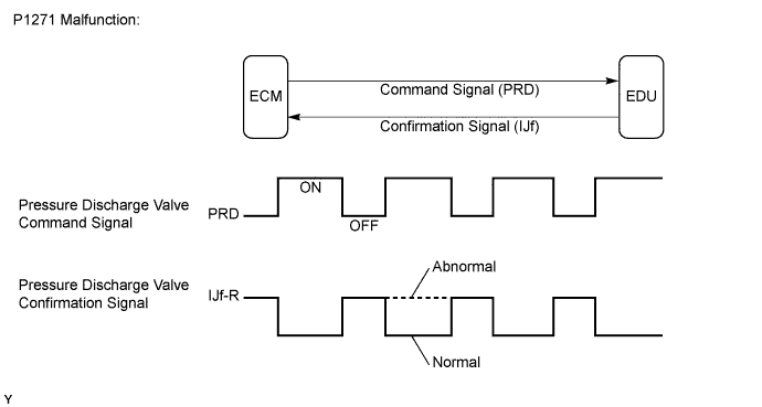
- P1271 (Open or short in pressure discharge valve circuit): This DTC will be set if there is no valve opening confirmation (IJf) signal sent from the EDU to the ECM, if the ECM has commanded the EDU to open the pressure discharge valve. This DTC refers to an open or short circuit malfunction of the pressure discharge valve circuit, not a malfunction that includes a valve that is stuck open or closed. The EDU monitors the current supplied to the pressure discharge valve to verify that the current flows into the valve. If the current exceeds the specified level, the EDU interprets this as the IJf signal is low. If this DTC is present, the ECM enters the fail-safe mode and limits engine power. The fail-safe mode continues until the ignition switch is turned off.
- P1272 (Closed malfunction of the pressure discharge valve): The pressure discharge valve will open and discharge the internal fuel pressure from the common rail to the fuel tank when the ignition switch is turned off. In this event, the ECM compares the actual drop rate of the internal fuel pressure and the target drop rate. If the ECM judges the actual drop rate is smaller than the target, the ECM then judges that the valve is stuck closed and sets this DTC. This DTC will be stored if the internal fuel pressure does not drop to the target after the ignition switch has been turned off. If this DTC is present, the ECM enters a fail-safe mode and limits engine power. The fail-safe mode continues until the ignition switch is turned off.
Monitor strategy
| Required sensors | EDU |
| Frequency of operation | Continuous |
| Duration | 3 seconds |
| MIL operation | 1 driving cycle |
| Required sensors | Fuel pressure sensor |
| Frequency of operation | Once per driving cycle |
| Duration | 1 second |
| MIL operation | 2 driving cycles |
Typical enabling conditions
| Specification |
| Drive the vehicle at 50 km/h (31 mph) in 3rd gear and then decelerate by completely releasing the accelerator pedal |
| Item | Specification | |
| Minimum | Maximum | |
| Fuel pressure | 30 MPa (306 kgf/cm2, 4,351 psi) | - |
| Fuel temperature | 0°C (32°F) | - |
| Battery voltage | 11 V | - |
| The monitor will not run if the fuel pressure sensor, pressure discharge valve circuit, or fuel temperature sensor is malfunctioning |
Typical malfunction thresholds
| Specification |
| There are no confirmation signals from the EDU, despite the ECM sending the command signals regularly during deceleration |
| Specification |
| The internal pressure stays beyond the specified level after the ignition switch was turned off |
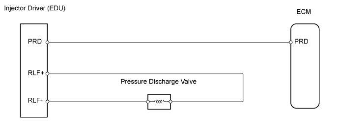
Wiring diagram
Inspection procedure
NOTICE:
After replacing the ECM, the new ECM needs registration and initialization.
HINT:
- After completing repairs, confirm that P1271 and/or P1272 does not recur.
- If P0200 and P1271 are present simultaneously, there is an open in the INJF wire harness between the EDU and ECM, or there is an open in the wire harness for both injector and pressure discharge valve.
-
Connect the intelligent tester to the DLC3.
-
Turn the ignition switch on (IG) and turn the tester ON.
-
Enter the following menus: Powertrain / Engine and ECT / DTC.
-
Read DTCs.
| Display (DTC Output) | Proceed to |
| P1271 and/or P1272 | A |
| P1272 | B |
|
|
||||
| A | |
-
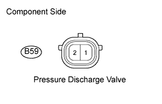
Disconnect the B59 pressure discharge valve connector.
-
Measure the resistance of the terminals of the pressure discharge valve.
Standard resistance:
Tester Connection Condition Specified Condition B59-1 - B59-2 20°C (68°F) 0.85 to 1.05 ? -
Reconnect the pressure discharge valve connector.
|
|
||||
| OK | |
-
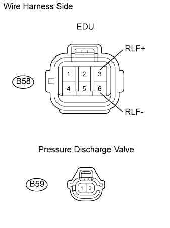
Disconnect the B58 EDU connector.
-
Disconnect the B59 pressure discharge valve connector.
-
Measure the resistance of the wire harness side connectors.
Standard resistance:
| Tester Connection | Specified Condition |
| B58-3 (RLF+) - B59-2 | Below 1 ? |
| B58-6 (RLF-) - B59-1 | Below 1 ? |
| B58-3 (RLF+) or B59-2 - Body ground | 10 k? or higher |
| B58-6 (RLF-) or B59-1 - Body ground | 10 k? or higher |
-
Reconnect the EDU connector.
-
Reconnect the pressure discharge valve connector.
|
|
||||
| OK | |
-
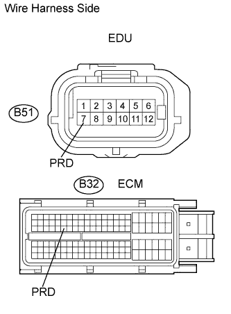
Disconnect the B51 EDU connector.
-
Disconnect the B32 ECM connector.
-
Measure the resistance of the wire harness side connectors.
Standard resistance:
| Tester Connection | Specified Condition |
| B51-7 (PRD) - B32-52 (PRD) | Below 1 ? |
| B51-7 (PRD) or B32-52 (PRD) - Body ground | 10 k? or higher |
-
Reconnect the EDU connector.
-
Reconnect the ECM connector.
|
|
||||
| OK | |
-
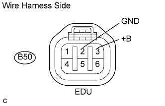
Disconnect the B50 EDU connector.
-
Turn the ignition switch on (IG).
-
Measure the voltage of the specified terminals of each EDU wire harness side connector.
Standard voltage:
| Tester Connection | Specified Condition |
| B50-3 (+B) - B50-2 (GND) | 9 to 14 V |
-
Reconnect the EDU connector.
|
|
||||
| OK | |
-
Replace the EDU.
| NEXT | |
-
Connect the intelligent tester to the DLC3.
-
Turn the ignition switch on (IG) and turn the tester ON.
-
Clear DTCs.
-
Start the engine and drive the vehicle for approximately 15 minutes.
-
Enter the following menus: Powertrain / Engine and ECT / DTC.
-
Read the DTCs.
| Display (DTC Output) | Proceed to |
| P1271 and/or P1272 | A |
| No output | B |
|
|
||||
| A | |
|
-
Replace the common rail assembly.
| NEXT | |
|