DTC P0405 Exhaust Gas Recirculation Sensor "A" Circuit Low
DTC P0406 Exhaust Gas Recirculation Sensor "A" Circuit High
Description
The EGR valve position sensor is mounted on the EGR valve and used for detecting the lift amount of the valve. The lift amount detected by the sensor is provided to the ECM as feedback. The ECM then regulates the lift amount of the valve in accordance with engine running conditions.
Toyota fault code list DTC P0405 DTC P0406
| DTC No. | DTC Detection Condition | Trouble Area |
| P0405 | EGR valve position sensor output voltage is less than 0.1 V for more than 5 seconds (1 trip detection logic) |
|
| P0406 | EGR valve position sensor output voltage is more than 4.9 V for more than 5 seconds (1 trip detection logic) |
|
HINT:
- After confirming DTCs P0405 and P0406, check the EGR valve opening angle condition by entering the following menus on the intelligent tester: Powertrain / Engine and ECT / Data List / EGR Position.
- The result values below are for when the ignition switch is on (IG) (engine is stopped), or when the engine is fully warmed-up and idling.
| Result | Condition |
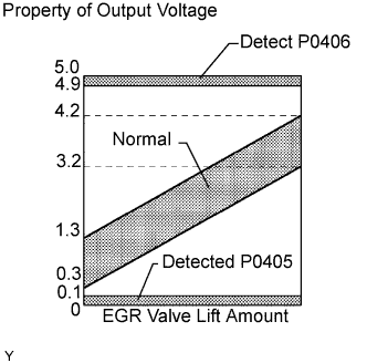
| Changes between 0.3 V and 4.2 V | Normal |
| Less than 0.1 V | P0405 (Low input voltage) |
| More than 4.9 V | P0406 (High input voltage) |
Monitor description DTC P0405 DTC P0406
When output voltage of the EGR valve position sensor deviates from the normal operating range of 0.1 to 4.9 V for more than 0.5 seconds, the ECM interprets this as a malfunction of the sensor circuit, and illuminates the MIL.
Wiring diagram
Inspection procedure DTC P0405 DTC P0406
NOTICE:
After replacing the ECM, the new ECM needs registration and initialization .
| 1.CHECK EGR VALVE POSITION SENSOR POWER SOURCE |
-
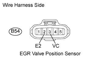
Disconnect the B54 EGR valve position sensor connector.
-
Measure the voltage of the wire harness side connector.
Standard voltage:
Tester Connection Specified Condition B54-3 (VC) - B54-2 (E2) 4.5 to 5.5 V -
Reconnect the EGR valve position sensor connector.
|
|
||||
| OK | |
| 2.INSPECT EGR VALVE POSITION SENSOR |
-
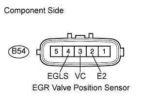
Disconnect the B54 EGR valve position sensor connector.
-
Measure the resistance of the EGR valve position sensor.
Standard resistance:
Tester Connection EGR Valve Condition Condition Specified Condition B54-3 (VC)- B54-2 (E2) - 20°C (68°F) 3.5 to 6.5 k? B54-4 (EGLS) - B54-2 (E2) Fully open 20°C (68°F) 3.9 k? B54-4 (EGLS) - B54-2 (E2) Fully closed 20°C (68°F) 1.0 k? -
Reconnect the EGR valve position sensor connector.
|
|
||||
| OK | |
| 3.CHECK WIRE HARNESS (EGR VALVE POSITION SENSOR - ECM) |
-
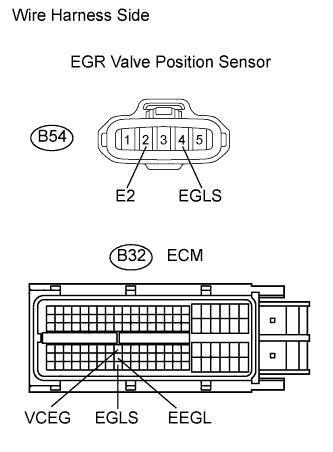
Disconnect the B54 sensor connector.
-
Disconnect the B32 ECM connector.
-
Measure the resistance of the wire harness side connectors.
Standard resistance:
Tester Connection Specified Condition B54-3 (VC) - B32-72 (VCEG) Below 1 ? B54-4 (EGLS) - B32-118 (EGLS) Below 1 ? B54-2 (E2) - B32-95 (EEGL) Below 1 ? B54-3 (VC) or B32-72 (VCEG) - Body ground 10 k? or higher B54-4 (EGLS) or B32-118 (EGLS) - Body ground 10 k? or higher -
Reconnect the EGR valve position sensor connector.
-
Reconnect the ECM connector.
|
|
||||
| OK | |
|