Топливная Форсунка -- Установка |
| 1. INSTALL INJECTOR ASSEMBLY |
Install 4 new nozzle seats to the cylinder head.
Install new O-rings to each injector.
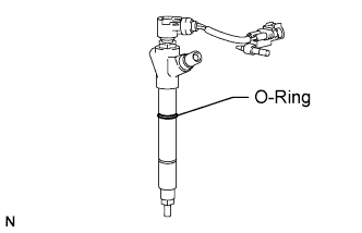 |
Apply a light coat of engine oil to the O-rings on each injector.
Install the 4 injectors to the cylinder head.
- ПРИМЕЧАНИЕ:
- Fit the injectors to the nozzle seats.
Temporarily install the 4 clamps to the cylinder head with the 4 bolts.
 |
Using a hexagon socket wrench, tighten the 4 bolts.
- Момент затяжки:
- 9 Н*м{92 кгс*см, 80 фунт-сила-дюймов}
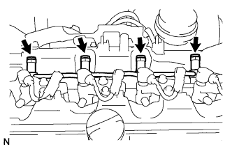
Install the nozzle holder clamps and washers as shown in the illustration.
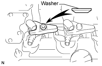 |
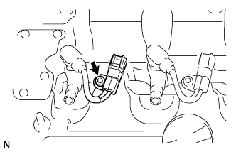
Temporarily install the nozzle holder clamp bolts.
- ПРИМЕЧАНИЕ:
- Pay attention to the mounting orientation (bevelled edge) of the washer.
- When temporarily attaching the nozzle holder clamp and the nozzle holder clamp bolt, be careful not to position them at an angle.
- УКАЗАНИЕ:
- Apply a light coat of engine oil to the threads of the nozzle holder clamp bolts.
Temporarily install the No. 1, No. 2, No. 3 and No. 4 injection pipes.
Temporarily install 4 new gaskets and the No. 1 nozzle leakage pipe assembly with the 4 union bolts.
Tighten the 4 nozzle holder clamp bolts.
- Момент затяжки:
- 25 Н*м{255 кгс*см, 18 фунт-сила-футов}
| 2. INSTALL NO. 1 NOZZLE LEAKAGE PIPE ASSEMBLY |
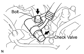
Temporarily install a new gasket, the fuel check valve and bolt.
 |
Tighten the 4 union bolts.
- Момент затяжки:
- 18 Н*м{184 кгс*см, 13 фунт-сила-футов}
 |
Tighten the fuel check valve and bolt.
- Момент затяжки:
- For fuel check valve:
- 32 Н*м{321 кгс*см, 23 фунт-сила-футов}
- For bolt:
- 21 Н*м{209 кгс*см, 15 фунт-сила-футов}
| 3. INSTALL NO. 1 INJECTION PIPE SUB-ASSEMBLY |
- ПРИМЕЧАНИЕ:
- In a case where an injector is replaced, the injection pipes must also be replaced.
Temporarily install the 4 injection pipes.
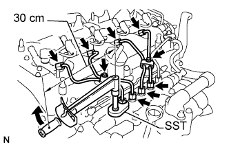 |
Using SST, first tighten the nut at the common rail end of the injection pipe.
- SST
- 09023-38401
- Момент затяжки:
- With SST:
- 27 Н*м{275 кгс*см, 20 фунт-сила-футов}
- Момент затяжки:
- Without SST:
- 30 Н*м{306 кгс*см, 22 фунт-сила-футов}
- УКАЗАНИЕ:
- Use of proper SST is required to ensure that the correct torque is applied to the injection pipe nut.
- Use a torque wrench with a fulcrum length of 30 cm (11.81 in.).
- Make sure that the pipe is not deformed or twisted during installation.
If the pipe is deformed or twisted, or if it cannot be installed properly, replace the pipe with a new one.
Using SST, tighten the nut at the injector end of the injection pipe.
- SST
- 09023-38401
- Момент затяжки:
- With SST:
- 27 Н*м{275 кгс*см, 20 фунт-сила-футов}
- Момент затяжки:
- Without SST:
- 30 Н*м{306 кгс*см, 22 фунт-сила-футов}
- УКАЗАНИЕ:
- Use of proper SST is required to ensure that the correct torque is applied to the injection pipe nut.
- Use a torque wrench with a fulcrum length of 30 cm (11.81 in.).
- Make sure that the pipe is not deformed or twisted during installation.
If the pipe is deformed or twisted, or if it cannot be installed properly, replace the pipe with a new one.
| 4. INSTALL NO. 2 INJECTION PIPE SUB-ASSEMBLY |
- УКАЗАНИЕ:
- Perform the same procedure as for the No. 1 injection pipe.
| 5. INSTALL NO. 3 INJECTION PIPE SUB-ASSEMBLY |
- УКАЗАНИЕ:
- Perform the same procedure as for the No. 1 injection pipe.
| 6. INSTALL NO. 4 INJECTION PIPE SUB-ASSEMBLY |
- УКАЗАНИЕ:
- Perform the same procedure as for the No. 1 injection pipe.
Install the 4 injection pipe clamps with the 2 bolts.
- Момент затяжки:
- 5.0 Н*м{51 кгс*см, 44 фунт-сила-дюймов}
| 7. CONNECT ENGINE WIRE |
Connect the engine wire to the engine cover bracket.
 |
Connect the glow plug harness.
Install the 2 nuts (*1).
Install the nut and grommet (*2).
- Момент затяжки:
- 2.2 Н*м{22 кгс*см, 19 фунт-сила-дюймов}
Connect the turbo pressure sensor connector (*3).
Connect the discharge valve connector (*4).
Connect the fuel pressure sensor connector (*5).
| 8. INSTALL NO. 1 ENGINE COVER |
Attach the 4 clips to install the engine cover.
- ПРИМЕЧАНИЕ:
- Line up the 4 grommets using the oil filler cap and oil dipstick as guides.
- Push down on the four locations shown to install the cover.
 |
| 9. REGISTRATION OF INJECTOR COMPENSATION CODE |
- УКАЗАНИЕ:
- Each injector assembly has a characteristic fuel injecting behavior (See page Нажмите здесь).
| 10. INSPECT FOR FUEL LEAK |
PERFORM ACTIVE TEST
Connect the intelligent tester to the DLC3.
Turn the ignition switch to the ON position.
Turn the intelligent tester on.
Enter the following menus: Powertrain / Engine / Active Test.
Perform the Active Test.
Tester Display Test Part Control Range Diagnostic Notes Test the Fuel Leak Pressurizing common rail internal fuel pressure, and checking for fuel leaks. Stop/Start - Fuel pressure inside common rail is pressurized to specified value and engine speed is increased to 2000 rpm when ON is selected.
- Above conditions are maintained while test is ON.
- Fuel pressure inside common rail is pressurized to specified value and engine speed is increased to 2000 rpm when ON is selected.