INSPECT CRANKSHAFT POSITION SENSOR
CHECK HARNESS AND CONNECTOR (CRANKSHAFT POSITION SENSOR - ECM)
CHECK CRANK POSITION SENSOR (SENSOR INSTALLATION)
CHECK CRANKSHAFT POSITION SENSOR PLATE (TEETH OF SENSOR PLATE)
DTC P0335 Crankshaft Position Sensor "A" Circuit
DTC P0339 Crankshaft Position Sensor "A" Circuit Intermittent
Description
The crankshaft position (CKP) sensor system consists of a crankshaft position sensor plate and a magnetic coil. The sensor plate has 34 teeth and is installed on the crankshaft. The pickup coil is made of windings, an iron core and magnet. The sensor plate rotates and as each tooth passes through the pickup coil, a pulse signal is created. The pickup coil generates 34 signals for each engine revolution. Based on these signals, the ECM calculates the crankshaft position and engine RPM. Using these calculations, the fuel injection time and ignition time are controlled.
| DTC No. | DTC Detection Condition | Trouble Area |
| P0335 |
|
|
| P0339 | Under conditions (a), (b) and (c), no CKP sensor signal to ECM for 0.05 seconds or more (1 trip detection logic): (a) Engine speed 1,000 rpm or more (b) Starter signal OFF (c) 3 seconds or more have lapsed since starter signal switched from ON to OFF |
|
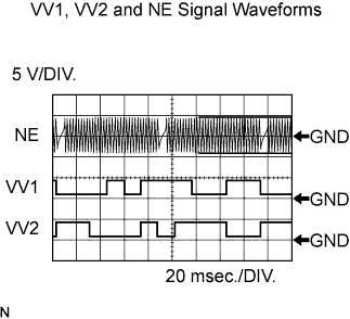
Reference: Inspection using an oscilloscope.
HINT:
- The correct waveform is as shown.
- VV1+ and VV2+ stands for the VVT sensor signal, and NE+ stands for the CKP sensor signal.
| Item | Content |
| Terminals | VV1+ - VV1- VV2+ - VV2- NE+ - NE- |
| Equipment Settings | 5 V/DIV, 20 ms./DIV. |
| Conditions | Cranking or idling |
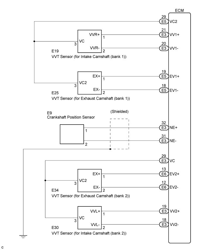
Wiring diagram
Inspection procedure
HINT:
- If no problem is found by this diagnostic troubleshooting procedure, troubleshooting the engine mechanical system.
- Check the engine speed. The engine speed can be checked by using the intelligent tester. To check, follow the operation below:
- Connect the intelligent tester to the DLC3.
- Start the engine.
- Turn the tester ON
- Enter the following menus: Power train / Engine / Data List / Engine Speed.
- The engine speed may be indicated as zero despite the engine revolving normally. This is caused by a lack of NE signals from the crankshaft position (CKP) sensor. Alternatively, the engine speed may be indicated as lower than the actual engine speed, if the CKP sensor output voltage is insufficient.
- Read freeze frame data using the intelligent tester. Freeze frame data records the engine conditions when malfunctions are detected. When troubleshooting, freeze frame data can help determine if the vehicle was running or stopped, if the engine was warmed up or not, if the air-fuel ratio was lean or rich, and other data from the time the malfunction occurred .
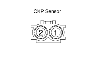
| 1.INSPECT CRANKSHAFT POSITION SENSOR |
-
Disconnect the E9 crankshaft position (CKP) sensor connector.
-
Measure the resistance of the CKP sensor.
Standard resistance:
Tester Connection Condition Specified Condition 1 - 2 Cold 1,630 to 2,740 ? 1 - 2 Hot 2,065 to 3,225 ? HINT:
Terms cold and hot refer to the temperature of the coils. Cold means approximately -10 to 50°C (14 to 122°F). Hot means approximately 50 to 100°C (122 to 212°F).
-
Reconnect the CKP sensor connector.
|
|
||||
| OK | |
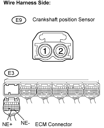
| 2.CHECK HARNESS AND CONNECTOR (CRANKSHAFT POSITION SENSOR - ECM) |
-
Disconnect the E9 CKP sensor connector.
-
Disconnect the E3 ECM connector.
-
Measure the resistance of the wire harness side connectors.
Standard resistance (Check for open):
Tester Connection Specified Condition E9-1 - NE+ (E3-32) Below 1 ? E9-2 - NE- (E3-31) Below 1 ? Standard resistance (Check for short):
Tester Connection Specified Condition E9-1 or NE+ (E3-32) - Body ground 10 k? or higher E9-2 or NE- (E3-31) - Body ground 10 k? or higher
-
Reconnect the ECM connector.
-
Reconnect the CKP sensor connector.
|
|
||||
| OK | |
| 3.CHECK CRANK POSITION SENSOR (SENSOR INSTALLATION) |
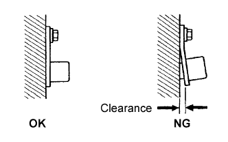
-
Check the CKP sensor installation.
OK:
Sensor is installed correctly.
|
|
||||
| OK | |
| 4.CHECK CRANKSHAFT POSITION SENSOR PLATE (TEETH OF SENSOR PLATE) |
-
Check the teeth of the sensor plate.
OK:
Sensor plate does not have any crack or deformation.
|
|
||||
| OK | ||
|
||