CHECK OTHER DTC OUTPUT (IN ADDITION TO DTC P0121)
DTC P0121 Throttle / Pedal Position Sensor / Switch "A" Circuit Range / Performance Problem
Description
HINT:
- This DTC relates to the Throttle Position (TP) sensor.
- This ETC (Electrical Throttle Control System) does not use a throttle cable.
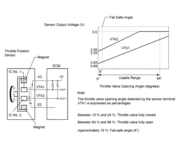
The Throttle Position (TP) sensor is mounted on the throttle body, and detects the opening angle of the throttle valve. This sensor is a non-contact type, and uses Hall-effect elements, in order to yield accurate signals, even in extreme driving conditions, such as at high speeds as well as very low speeds. The TP sensor has two sensor circuits which each transmits a signal, VTA1 and VTA2. VTA1 is used to detect the throttle valve angle and VTA2 is used to detect malfunctions in VTA1. The sensor signal voltages vary between 0 V and 5 V in proportion to the throttle valve opening angle, and are transmitted to the VTA terminals of the ECM. As the valve closes, the sensor output voltage decreases and as the valve opens, the sensor output voltage increases. The ECM calculates the throttle valve opening angle according to these signals and controls the throttle actuator in response to driver inputs. These signals are also used in calculations such as air-fuel ratio correction, power increase correction and fuel-cut control.
| DTC No. | DTC Detection Condition | Trouble Area |
| P0121 | Difference between VTA1 and VTA2 voltages less than 0.8 V, or more than 1.6 V for 2 seconds (1 trip detection logic) | TP sensor (built into throttle body) |
FAIL-SAFE
When this DTC, as well as other DTCs relating to ETCS (Electronic Throttle Control System) malfunctions, is set, the ECM enters fail-safe mode. During fail-safe mode, the ECM cuts the current to the throttle actuator off, and the throttle valve is returned to a 6° throttle angle by the return spring. The ECM then adjusts the engine output by controlling the fuel injection (intermittent fuel-cut) and ignition timing, in accordance with the accelerator pedal opening angle, to allow the vehicle to continue at a minimal speed. If the accelerator pedal is depressed firmly and gently, the vehicle can be driven slowly. Fail-safe mode continues until a pass condition is detected, and the engine switch is then turned to off.
Inspection procedure
HINT:
Read freeze frame data using the intelligent tester. Freeze frame data records the engine conditions when malfunctions are detected. When troubleshooting, freeze frame data can help determine if the vehicle was moving or stationary, if the engine was warmed up or not, if the air-fuel ratio was lean or rich, and other data from the time the malfunction occurred .
| 1.CHECK OTHER DTC OUTPUT (IN ADDITION TO DTC P0121) |
-
Connect the intelligent tester to the DLC3.
-
Turn the engine switch on (IG).
-
Turn the tester ON.
-
Enter the following menus: Power train / Engine / DTC.
-
Read the DTC.
Result:
Display (DTC output) Proceed to P0121 A P0121 and other DTCs B
|
|
||||
| A | ||
|
||