INSPECT HEATED OXYGEN SENSOR (HEATER RESISTANCE)
INSPECT INTEGRATION RELAY (EFI MAIN RELAY)
INSPECT ECM (HT1B OR HT2B VOLTAGE)
CHECK HARNESS AND CONNECTOR (HEATED OXYGEN SENSOR - EFI NO. 2 FUSE)
CHECK HARNESS AND CONNECTOR (HEATED OXYGEN SENSOR - ECM)
DTC P0037 Oxygen Sensor Heater Control Circuit Low (Bank 1 Sensor 2)
DTC P0038 Oxygen Sensor Heater Control Circuit High (Bank 1 Sensor 2)
DTC P0057 Oxygen Sensor Heater Control Circuit Low (Bank 2 Sensor 2)
DTC P0058 Oxygen Sensor Heater Control Circuit High (Bank 2 Sensor 2)
Description
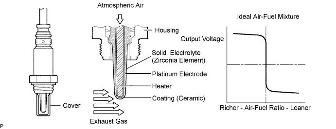
In order to obtain a high purification rate of the carbon monoxide (CO), hydrocarbon (HC) and nitrogen oxide (NOx) components in the exhaust gas, a TWC (Three-Way Catalytic Converter) is used. For the most efficient use of the TWC, the air-fuel ratio must be precisely controlled so that it is always close to the stoichiometric air-fuel level. For the purpose of helping the ECM to deliver accurate air-fuel ratio control, a Heated Oxygen (HO2) sensor is used. The HO2 sensor is located behind the TWC, and detects the oxygen concentration in the exhaust gas. Since the sensor is integrated with the heater that heats the sensing portion, it is possible to detect the oxygen concentration even when the intake air volume is low (the exhaust gas temperature is low). When the air-fuel ratio becomes lean, the oxygen concentration in the exhaust gas is rich. The HO2 sensor informs the ECM that the post-TWC air-fuel ratio is lean (low voltage, i.e. less than 0.45 V). Conversely, when the air-fuel ratio is richer than the stoichiometric air-fuel level, the oxygen concentration in the exhaust gas becomes lean. The HO2 sensor informs the ECM that the post-TWC air-fuel ratio is rich (high voltage, i.e. more than 0.45 V). The HO2 sensor has the property of changing its output voltage drastically when the air-fuel ratio is close to the stoichiometric level. The ECM uses the supplementary information from the HO2 sensor to determine whether the air-fuel ratio after the TWC is rich or lean, and adjusts the fuel injection time accordingly. Thus, if the HO2 sensor is working improperly due to internal malfunctions, the ECM is unable to compensate for deviations in the primary air-fuel ratio control.
HINT:
- Sensor 2 refers to the sensor mounted behind the Three-Way Catalytic Converter (TWC) and located far from the engine assembly.
- When any of these DTCs are set, the ECM enters fail-safe mode. The ECM turns off the Heated Oxygen (HO2) Sensor heater in fail-safe mode. Fail-safe mode continues until the engine switch is turned off.
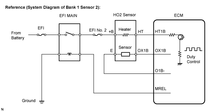
- The ECM provides a pulse width modulated control circuit to adjust the current through the heater. The HO2 sensor heater circuit uses a relay on the B+ side of the circuit.
| DTC No. | DTC Detection Condition | Trouble Area |
| P0037 P0057 |
Heated Oxygen (HO2) sensor heater current less than 0.3 A (1 trip detection logic) |
|
| P0038 P0058 |
Heated Oxygen (HO2) sensor heater current more than 2 A (1 trip detection logic) |
|
HINT:
- Bank 1 refers to the bank that includes cylinder No. 1.
- Bank 2 refers to the bank that does not include cylinder No. 1.
- Sensor 1 refers to the sensor closest to the engine assembly.
- Sensor 2 refers to the sensor farthest away from the engine assembly.
Wiring diagram
Refer to DTC P0136 .
Inspection procedure
HINT:
Read freeze frame data using the intelligent tester. Freeze frame data records the engine conditions when malfunctions are detected. When troubleshooting, freeze frame data can help determine if the vehicle was moving or stationary, if the engine was warmed up or not, if the air-fuel ratio was lean or rich, and other data from the time the malfunction occurred .
| 1.INSPECT HEATED OXYGEN SENSOR (HEATER RESISTANCE) |
-
Disconnect the J68*1 or J40*2 heated oxygen (HO2) sensor connectors.
HINT:
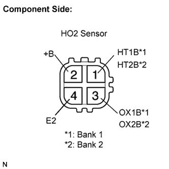
- *1: Bank 1 Sensor 2
- *2: Bank 2 Sensor 2
-
Measure the resistance of the HO2 sensor connector.
Standard resistance (Bank 1 sensor 2):
Tester Connection Condition Specified Condition HT1B (1) - +B (2) 20°C (68°F) 11 to 16 ? HT1B (1) - E2 (4) - 10 k? or higher Standard resistance (Bank 2 sensor 2):
Tester Connection Condition Specified Condition HT2B (1) - +B (2) 20°C (68°F) 11 to 16 ? HT2B (1) - E2 (4) - 10 k? or higher
-
Reconnect the HO2 sensor connector.
|
|
||||
| OK | |
| 2.INSPECT INTEGRATION RELAY (EFI MAIN RELAY) |
-
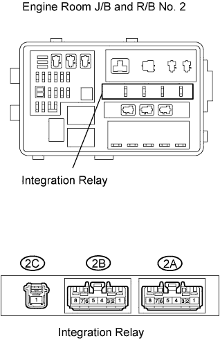
Remove the integration relay from the engine room J/B and R/B No. 2.
-
Inspect the EFI MAIN relay.
Standard resistance:
Terminal Connection Specified Condition 2A-8 - 2A-5 10 k? or higher 2A-8 - 2A-5 Below 1 ?
(when battery voltage applied to terminals 2A-7 and 2A-6)
-
Reinstall the integration relay.
|
|
||||
| OK | |
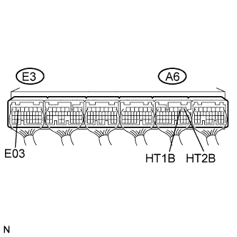
| 3.INSPECT ECM (HT1B OR HT2B VOLTAGE) |
-
Turn the engine switch on (IG).
-
Measure the voltage of the A6 and E3 ECM connectors.
Standard voltage:
Terminal Connection Specified Condition HT1B (A6-2) - E03 (E3-6) 9 to 14 V HT2B (A6-1) - E03 (E3-6) 9 to 14 V
HINT:
- The HT1B means the heated oxygen sensor bank 1 sensor 2.
- The HT2B means the heated oxygen sensor bank 2 sensor 2.
|
|
||||
| NG | |
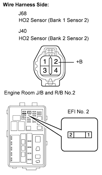
| 4.CHECK HARNESS AND CONNECTOR (HEATED OXYGEN SENSOR - EFI NO. 2 FUSE) |
-
Check the harness and connector between the HO2 sensor and EFI No. 2 fuse.
-
Disconnect the J68*1 or J40*2 HO2 sensor connector.
HINT:
- *1: Bank 1 Sensor 2
- *2: Bank 2 Sensor 2
-
Remove the EFI No. 2 fuse from the engine room J/B and R/B No. 2.
-
Measure the resistance of the wire harness side connectors.
Standard resistance:
Terminal Connection Specified Condition +B (J68-2) - EFI No. 2 fuse (2) Below 1 ? +B (J40-2) - EFI No. 2 fuse (2) Below 1 ? Standard resistance:
Terminal Connection Specified Condition +B (J68-2) or EFI No .2 fuse (2) - Body ground 10 k? or higher +B (J40-2) or EFI No. 2 fuse (2) - Body ground 10 k? or higher -
Reconnect the HO2 sensor connector.
-
Reconnect the EFI No. 2 fuse.
-
|
|
||||
| OK | |
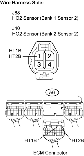
| 5.CHECK HARNESS AND CONNECTOR (HEATED OXYGEN SENSOR - ECM) |
-
Check the harness and connector between the ECM and HO2 sensor.
-
Disconnect the J68*1 or J40*2 HO2 sensor connector.
HINT:
- *1: Bank 1 Sensor 2
- *2: Bank 2 Sensor 2
-
Disconnect the A6 ECM connector.
-
Measure the resistance of the wire harness side connectors.
Standard resistance:
Terminal Connection Specified Condition HT1B (J68-1) - HT1B (A6-2) Below 1 ? HT2B (J40-1) - HT2B (A6-1) Below 1 ? Standard resistance:
Terminal Connection Specified Condition HT1B (J68-1) or HT1B (A6-2) - Body ground 10 k? or higher HT2B (J40-1) or HT2B (A6-1) - Body ground 10 k? or higher -
Reconnect the HO2 sensor connector.
-
Reconnect the ECM connector.
-
|
|
||||
| OK | ||
|
||