Generator -- Installation |
| 1. INSTALL GENERATOR ASSEMBLY |
Install the stud bolt.
- Torque:
- 10 N*m{102 kgf*cm, 7 ft.*lbf}
Install the generator with the 3 bolts and nut.
- Torque:
- 43 N*m{438 kgf*cm, 32 ft.*lbf}
Connect the harness bracket to the generator with the bolt.
- Torque:
- 31 N*m{316 kgf*cm, 23 ft.*lbf}
Connect the generator wire with the nut.
- Torque:
- 9.8 N*m{100 kgf*cm, 87 in.*lbf}
Close the terminal cap.
Connect the generator connector.
| 2. CONNECT OIL COOLER PIPE ASSEMBLY |
Connect the oil cooler pipe with the 2 bolts.
- Torque:
- 14 N*m{143 kgf*cm, 10 ft.*lbf}
| 3. CONNECT VANE PUMP ASSEMBLY |
 |
- HINT:
- Before performing the following procedures, move the spacer until the vane pump can be installed.
| *1 | Spacer |
Connect the vane pump to the timing chain cover with the 2 bolts.
- Torque:
- 21 N*m{214 kgf*cm, 15 ft.*lbf}
| 4. INSTALL AIR CLEANER ASSEMBLY |
Install the air cleaner with the 3 bolts.
- Torque:
- 5.0 N*m{51 kgf*cm, 44 in.*lbf}
| 5. INSTALL AIR CLEANER HOSE ASSEMBLY |
Install the air cleaner hose so that the protrusion of the air cleaner cap aligns with the groove of the hose as shown in the illustration.
Text in Illustration *1 Groove *2 Protrusion
 |
Tighten the 2 clamps.
- Torque:
- 2.5 N*m{25 kgf*cm, 22 in.*lbf}
Connect the vacuum hose.
Connect the No. 2 ventilation hose.
| 6. INSTALL FRONT FENDER APRON SEAL FRONT RH |
Install the fender apron seal with the 3 clips.
| 7. INSTALL FAN AND GENERATOR V BELT |
Set the V belt onto every part.
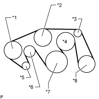 |
While turning the belt tensioner counterclockwise, remove the bar.
Text in Illustration *1 Vane Pump *2 Water Pump *3 No. 1 Idler *4 Fan *5 Generator *6 Belt Tensioner *7 Crankshaft *8 Cooler Compressor - NOTICE:
- Make sure that the V belt is properly set to each pulley.
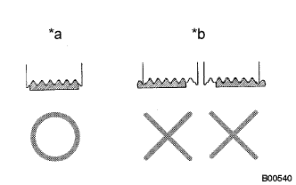
After installing the belt, check that it fits properly in the ribbed grooves.
Text in Illustration *a CORRECT *b INCORRECT - HINT:
- Make sure to check by hand that the belt has not slipped out of the grooves on the bottom of the pulley.
 |
| 8. INSTALL NO. 1 ENGINE UNDER COVER SUB-ASSEMBLY |
Install the No. 1 engine under cover with the 10 bolts.
- Torque:
- 29 N*m{296 kgf*cm, 21 ft.*lbf}
| 9. INSTALL FRONT FENDER SPLASH SHIELD SUB-ASSEMBLY LH |
Push in the clip to install the front fender splash shield sub-assembly LH.
Install the 3 bolts and screw.
| 10. INSTALL FRONT FENDER SPLASH SHIELD SUB-ASSEMBLY RH |
Push in the clip to install the front fender splash shield sub-assembly RH.
Install the 3 bolts and 2 screws.
| 11. CONNECT CABLE TO NEGATIVE BATTERY TERMINAL |
- NOTICE:
- When disconnecting the cable, some systems need to be initialized after the cable is reconnected (Click here).
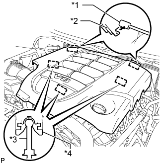
| 12. INSTALL V-BANK COVER SUB-ASSEMBLY |
Attach the 2 V-bank cover hooks to the bracket. Then align the 3 V-bank cover grommets with the 3 pins, and press down on the V-bank cover to attach the pins.
Text in Illustration *1 Bracket *2 Hook *3 Pin *4 Grommet
 |