Fuel supply pump 2AD-FHV
Components
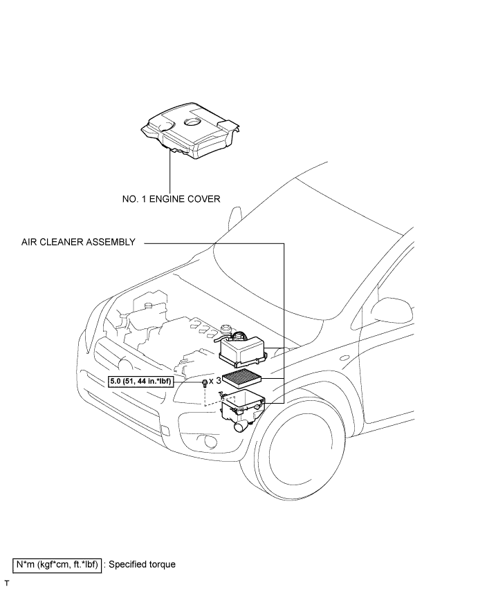
Fuel supply pump 2AD-FHV
Removal
CAUTION:
Wait at least 90 seconds after disconnecting the cable from the negative (-) battery terminal to prevent airbag and seat belt pretensioner activation.
-
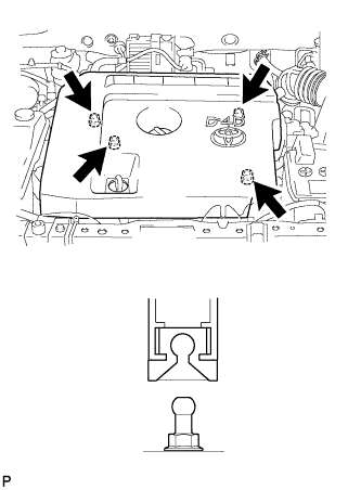
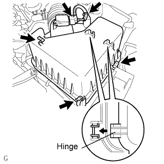
Detach the 4 clips and remove the engine cover.
-
Disconnect the mass air flow meter connector.
-
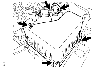
Unhook the 3 hook clamps.
-
Disengage the wire harness clamp.
-
Using pliers, grip the claws of the clip and slide the clip to disconnect the PCV hose from the cylinder head cover.
-
Using pliers, grip the claws of the clip to remove the air cleaner cap.
-
Remove the air filter element.
-
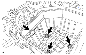
Disconnect the wire harness clamp and remove the 3 bolts and air cleaner case.
-
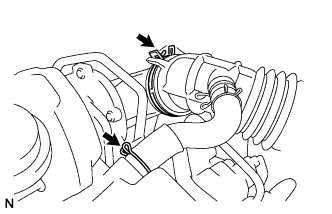
Using pliers, grip the claws of the 2 clips and slide the 2 clips to remove the No. 3 fuel hose.
-
Disconnect the exhaust fuel addition injector connector.
-
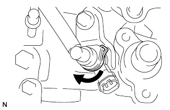
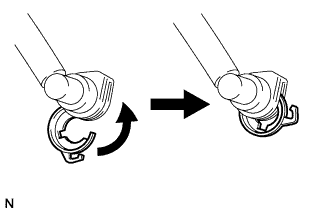
Turn the retainer as shown in the illustration.
-
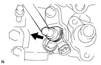
Disconnect the fuel tube from the exhaust fuel addition injector connector.
-
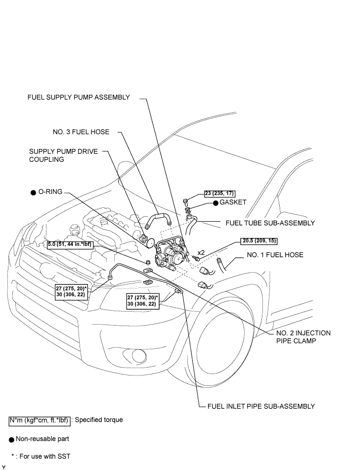
Remove the union bolt, gasket and fuel tube.
-
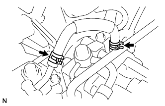
Using pliers, grip the claws of the 2 clips and slide the 2 clips to remove the No. 1 fuel hose.
NOTICE:
After removing the fuel inlet pipe, cover the common rail and supply pump with electrical tape to prevent dirt from entering them.
-
Remove the nut and fuel inlet pipe clamps.
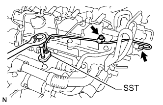
-
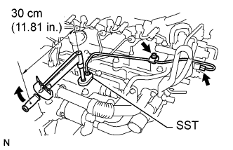
Using SST, remove the fuel inlet pipe.
SST:
09023-38401
-
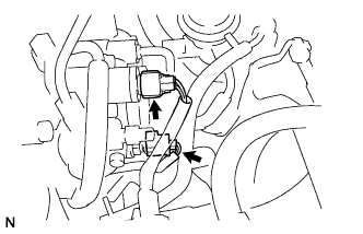
Disconnect the fuel temperature sensor connector.
-
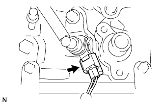
Disconnect the suction control valve connector.
-
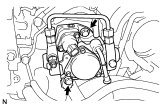
Remove the 2 bolts to remove the supply pump, O-ring and supply pump drive coupling from the cylinder head.
-
Remove the O-ring from the supply pump.
Fuel supply pump 2AD-FHV
Inspection
-
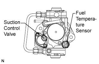
Inspect the suction control valve.
-
Measure the resistance of the valve.
Standard resistance:
Tester Connection Condition Specified Condition 1 - 2 20°C (68°F) 1.9 to 2.3 ? HINT:
The temperature indicated in "Condition" is the temperature of the suction control valve.
If the result is not as specified, replace the supply pump assembly. -
-
Inspect the fuel temperature sensor.
-
Measure the resistance of the sensor.
-
Standard resistance:
| Tester Connection | Condition | Specified Condition |
| 1 - 2 | 20°C (68 °F) | 2.32 to 2.59 ? |
| 1 - 2 | 80°C (176 °F) | 0.310 to 0.326 ? |
If the result is not as specified, replace the supply pump assembly.
Fuel supply pump 2AD-FHV
Installation
-
Install a new O-ring to the supply pump.
-
Install the supply pump drive coupling.
NOTICE:
When reusing the coupling, it must be installed in the same orientation (top/bottom, front/back) as when it was removed,
HINT:
Line up the coupling with the groove in the camshaft end.
-
Install the supply pump with the 2 bolts.
Torque:
20.5 N*m{ 209 kgf*cm , 15 ft.*lbf }
NOTICE:
Apply engine oil on the O-ring of the supply pump.
HINT:
Line up the end of the supply pump drive shaft with the supply pump drive coupling.
-
Connect the suction control valve connector.
-
Connect the fuel temperature sensor connector.
NOTICE:
In a case where the supply pump is replaced, the fuel inlet pipe must also be replaced.
-
Temporarily install the fuel inlet pipe with the 2 clamps and nut.
-
Using SST, first tighten the nut at the common rail end of the fuel inlet pipe.
SST:
09023-38401
Torque:
27 N*m{ 275 kgf*cm , 20 ft.*lbf }
HINT:
- Use of the proper SST is required to ensure that the correct torque is applied to the inlet pipe nut.
- Use a torque wrench with a fulcrum length of 30 cm (11.81 in.).
- Make sure that the pipe is not deformed or twisted during installation.
- If the pipe is deformed or twisted, or if it cannot be installed properly, replace the pipe with a new pipe.
-
Using SST, tighten the nut at the supply pump end of the fuel inlet pipe.
SST:
09023-38401
Torque:
27 N*m{ 275 kgf*cm , 20 ft.*lbf }
HINT:
- Use of the proper SST is required to ensure that the correct torque is applied to the inlet pipe nut.
- Use a torque wrench with a fulcrum length of 30 cm (11.81 in.).
- Make sure that the pipe is not deformed or twisted during installation.
- If the pipe is deformed or twisted, or if it cannot be installed properly, replace the pipe with a new pipe.
-
Tighten the fuel inlet pipe clamp nut.
Torque:
5.0 N*m{ 51 kgf*cm , 44 lbsf.in }
-
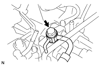
Install a new gasket and the fuel tube with the union bolt.
Torque:
23 N*m{ 235 kgf*cm , 17 ft.*lbf }
-
Turn the retainer in the direction indicated by the arrow until the retainer stops.
-
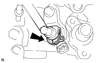
Insert the fuel tube connector into the injector.
-
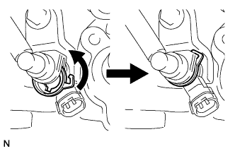
Turn the retainer in the direction indicated by the arrow until it makes a "click" sound.
NOTICE:
If the fuel tube connector is not inserted to the correct position in the injector, the retainer cannot be turned farther in the direction of the arrow.
-
Connect the exhaust fuel addition injector connector.
-
Using pliers, grip the claws of the 2 clips and slide the 2 clips to install the No. 1 fuel hose.
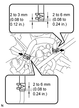
-
Using pliers, grip the claws of the 2 clips and slide the 2 clips to install the No. 3 fuel hose as shown in the illustration.
-
Install the cleaner case with the 3 bolts and connect the wire harness clamp.
Torque:
5.0 N*m{ 51 kgf*cm , 44 lbsf.in }
-
Install the air filter element.
-
Using pliers, grip the claws of the clip to install the air cleaner cap.
-
Using pliers, grip the claws of the clip and slide the clip to connect the PCV hose.
-
Insert the hinge parts of the air cleaner cap into the air cleaner case, and then hang the 3 hook clamps.
-
Connect the mass air flow meter connector.
-
Attach the wire harness clamp.
-
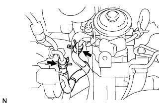
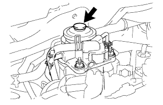
Using the hand pump indicated by the arrows in the illustration, bleed the fuel system. Continue pumping until pumping becomes difficult.
-
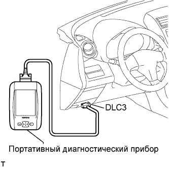
Perform the ACTIVE TEST.
-
Connect the intelligent tester to the DLC3.
-
Turn the ignition switch on (IG).
-
Turn the intelligent tester ON.
-
Enter the following menus: Powertrain / Engine / Active Test.
-
Perform the Active Test.
Intelligent Tester Display Test Details Control Range Diagnostic Notes Test the Fuel Leak Pressurizing common rail internal fuel pressure, and checking for fuel leaks Stop/Start - Fuel pressure inside common rail pressurized to specified value and engine speed increased to 2,000 rpm when Start is selected
- Above conditions to be maintained while test is Start
-
-
Attach the 4 clips to install the engine cover.