Engine unit 2AD-FHV
Replacement
-
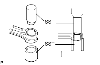
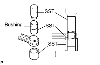
Using SST and a press, push out the bush.
SST:
09222-54011 (09222-03016, 09222-03026)
-
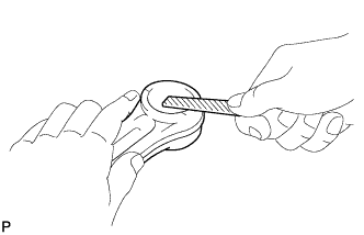
Using a round file, lightly file off any roughness from the small end of the connecting rod.
-
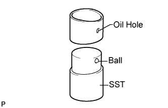
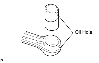
Attach a new bush to SST with the ball of SST inside the oil hole of the bush.
SST:
09222-54011 (09222-03021)
-
Align the oil holes of the bush and connecting rod.
-
Using SST and a press, push in the bush.
SST:
09222-54011 (09222-03016, 09222-03026, 09222-03021)
-
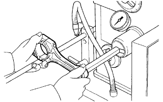
Using a pin hole grinder, hone the bush to obtain the standard specified clearance between the bush and piston pin.
-
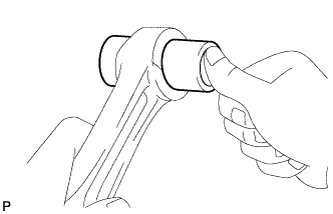
Check that the piston pin fits at normal room temperature.
-
Coat the piston pin with engine oil, and push it into the connecting rod with your thumb.
-
-
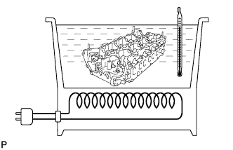
Gradually heat the cylinder head to approximately 80 to 100°C (176 to 212°F).
-
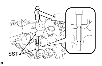
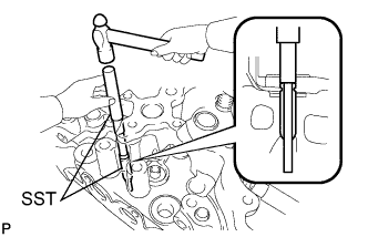
Using SST and a hammer, tap out the valve guide bush.
SST:
09201-10000 09950-70010
-
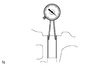
Using a caliper gauge, measure the bush bore diameter of the cylinder head.
-
Select a new guide bush (STD or O/S 0.05).
Bush bore diameter:
Bush size Specified Condition Use STD 10.985 to 11.006 mm (0.4324 to 0.4333 in.) Use O/S 0.05 11.056 to 11.065 mm (0.4353 to 0.4356 in.) HINT:
- If the bush bore diameter of the cylinder head is greater than 11.006 mm (0.4333 in.), machine the bush bore diameter to between 11.056 and 11.065 mm (0.4353 to 0.4356 in.).
- If the bush bore diameter of the cylinder head is greater than 11.065 mm (0.4356 in.), replace the cylinder head.
-
Gradually heat the cylinder head to approximately 80 to 100°C (176 to 212°F).
-
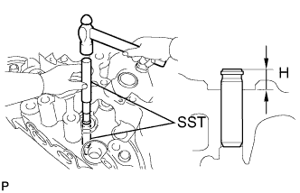
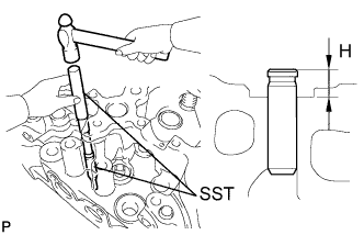
Using SST and a hammer, tap in a new guide bush to the specified protrusion height.
SST:
09201-10000 09950-70010
Standard protrusion height (H):
9.0 to 9.4 mm (0.354 to 0.370 in.)
-
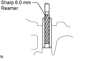
Using a sharp 6.0 mm reamer, ream the guide bush to obtain the standard specified clearance between the guide bush and valve stem.
-
Gradually heat the cylinder head to approximately 80 to 100°C (176 to 212°F).
-
Using SST and a hammer, tap out the valve guide bush.
SST:
09201-10000 09950-70010
-
Using a caliper gauge, measure the bush bore diameter of the cylinder head.
-
Select a new guide bush (STD or O/S 0.05).
Standard bush bore diameter:
Bush Size Specified Condition Use STD 11.006 to 11.015 mm (0.4333 to 0.4337 in.) Use O/S 0.05 11.056 to 11.065 mm (0.4353 to 0.4356 in.) HINT:
- If the bush bore diameter of the cylinder head is greater than 11.015 mm (0.4337 in.), machine the bush bore diameter to between 11.056 and 11.065 mm (0.4353 to 0.4356 in.).
- If the bush bore diameter of the cylinder head is greater than 11.065 mm (0.4356 in.), replace the cylinder head.
-
Gradually heat the cylinder head to approximately 80 to 100°C (176 to 212°F).
-
Using SST and a hammer, tap in a new guide bush to the specified protrusion height.
SST:
09201-10000 09950-70010
Standard protrusion height (H):
10.3 to 10.7 mm (0.406 to 0.421 in.)
-
Using a sharp 6.0 mm reamer, ream the guide bush to obtain the standard specified clearance between the guide bush and valve stem.
NOTICE:
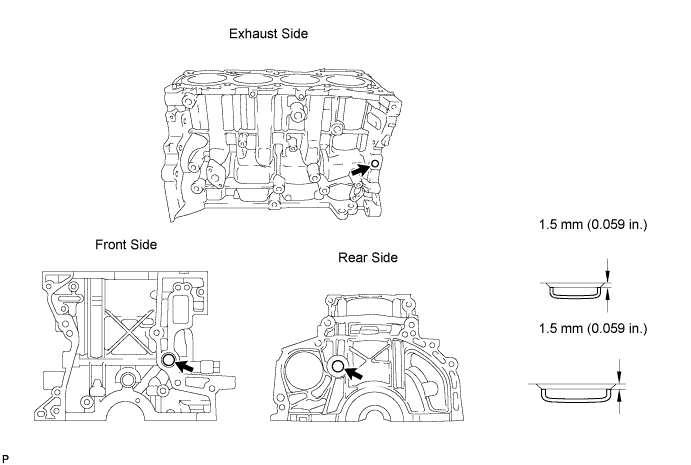
If water leaks from the tight plug or the plug corrodes, replace it.
-
Remove the tight plugs.
-
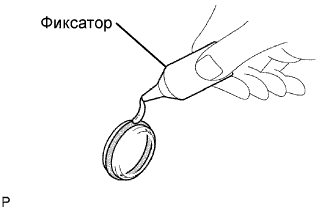
Apply adhesive around the tight plug.
Adhesive:
Toyota genuine adhesive 1324, three bond 1324 or equivalent
-
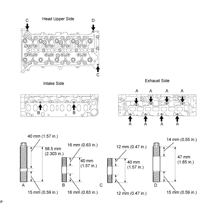
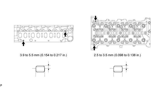
Using SST and a hammer, tap in 3 new tight plugs shown in the illustration.
SST:
09950-60010 09950-70010
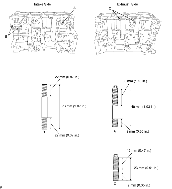
NOTICE:
If the stud bolt is deformed or the threads are damaged, replace it.
-
Remove the stud bolts.
-
Using an E5 "torx" socket wrench, install stud bolts A and C.
Torque:
3.0 N*m{ 31 kgf*cm , 27 lbsf.in } for bolt A
2.0 N*m{ 20 kgf*cm , 18 lbsf.in } for bolt C
-
Apply adhesive to the hole for stud bolt B on the cylinder block. Install stud bolts B.
Torque:
20 N*m{ 204 kgf*cm , 15 ft.*lbf }
-
Apply adhesive to the hole for the stud bolt on the cylinder block. Install the 2 stud bolts to the crankshaft bearing cap.
Torque:
5.0 N*m{ 51 kgf*cm , 44 lbsf.in }
NOTICE:
It is not necessary to remove with straight pin unless it is being replaced.
-
Remove the straight pin.
-
Using a plastic-faced hammer, tap in new straight pins to the cylinder block.

-
Using a plastic-faced hammer, tap in new ring pins to the crankshaft bearing cap.
NOTICE:
It is not necessary to remove the ring pin unless it is being replaced.
-
Remove the ring pins.
-
Using a plastic-faced hammer, tap in a new ring pin until the pin stops.
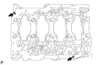
NOTICE:
If water leaks from the tight plug or the plug corrodes, replace it.
-
Remove the tight plugs.
-
Apply adhesive to the tight plug hole of the cylinder head.
Adhesive:
Toyota genuine adhesive 1324, three bond 1324 or equivalent
-
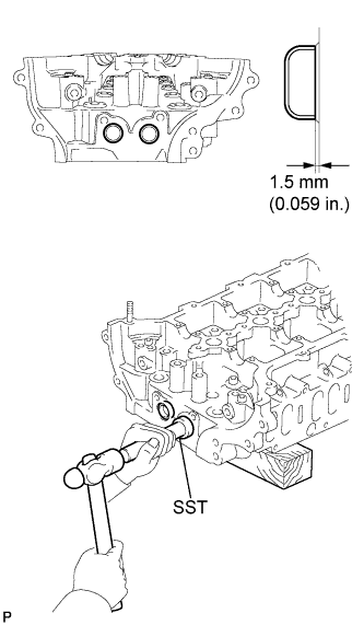
Using SST, tap in a new tight plug to the cylinder head as shown in the illustration.
SST:
09950-60010 09950-70010
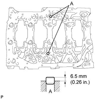
NOTICE:
If the stud bolt is deformed or the threads are damaged, replace it.
-
Remove the stud bolts.
-
Using an E8 "torx" socket wrench, install the stud bolts.
Torque:
12 N*m{ 122 kgf*cm , 9 ft.*lbf } for stud bolt A and B
5.0 N*m{ 51 kgf*cm , 44 lbsf.in } for stud bolt C
8.0 N*m{ 82 kgf*cm , 71 lbsf.in } for stud bolt D