DTC P2A00 Низкое быстродействие датчика A/F (датчик 1 ряда 1)
УКАЗАНИЕ:
Датчик 1 обозначает датчик, установленный в передней части трехкомпонентного каталитического нейтрализатора (TWC) и расположенный рядом с двигателем.
P2A00. Описание
См. страницу Ошибка P2195 .
| № ошибки | Условие обнаружения ошибки | Неисправный участок |
| P2A00 | Вычисленное значение степени износа на основании времени реакции датчика соотношения воздух-топливо (датчика кислорода) ниже порогового значения (логика диагностирования за 2 поездки) |
|
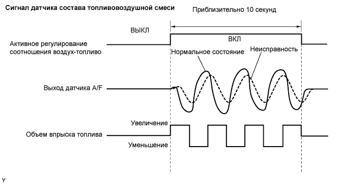
P2A00. Описание монитора
После прогрева двигателя ECM осуществляет обратную связь по соотношению воздух-топливо для поддержания на уровне, близком к стехиометрическому. Кроме этого, после выполнения необходимых условий осуществляется активное регулирование соотношения воздух-топливо в течение приблизительно 10 секунд для измерения времени отклика датчика кислорода. Во время выполнения активного регулирования соотношения воздух-топливо ECM принудительно повышает и понижает объем впрыска топлива на определенное количество на основании стехиометрического соотношения, вычисленного в ходе выполнения обычного регулирования соотношения воздух-топливо, и измеряет время реакции датчика кислорода. Во время активного регулирования соотношения воздух-топливо ECM получает сигнал датчика кислорода и использует его для вычисления степени износа на основании времени реакции датчика кислорода.
Если время реакции датчика кислорода о степени износа ниже порогового значения, ЕСМ воспринимает это как неисправность и регистрирует ошибку.
P2A00. Поездка в проверочном режиме
УКАЗАНИЕ:
Поездка в проверочном режиме активирует контроль времени реакции датчика кислорода.
 (а) Подсоедините портативный диагностический прибор к разъему DLC3.
- (b) Включите зажигание (IG).
- (с) Включите портативный диагностический прибор.
- (d) Сбросьте коды DTC (при наличии) .
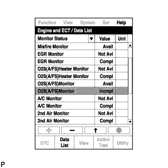
- (е) Выберите следующие элементы меню: Powertrain / Engine and ECT / Data List / Monitor Status.
- (f) Убедитесь, что для параметра "O2S(A/FS) Monitor" указывается состояние "Incmpl." (не завершено).
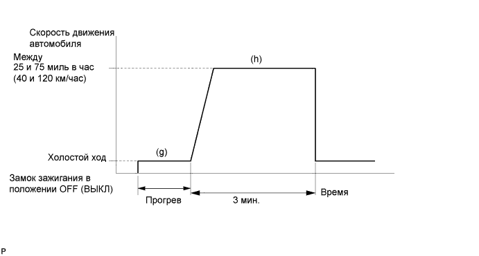
- (g) Запустите и прогрейте двигатель.
- (h) Совершите поездку на автомобиле со скоростью 25-75 миль в час (40-120 км/ч) длительностью 3 минуты.
- (i) Убедитесь, что для параметра "O2S(A/FS) Monitor" указывается состояние "Compl." (завершено).
- (j) Выберите следующие меню: Powertrain / Engine and ECT / DTC.
- (k) Проверьте, выводятся ли какие-либо коды DTC (какие-либо ожидающие обработки коды DTC).
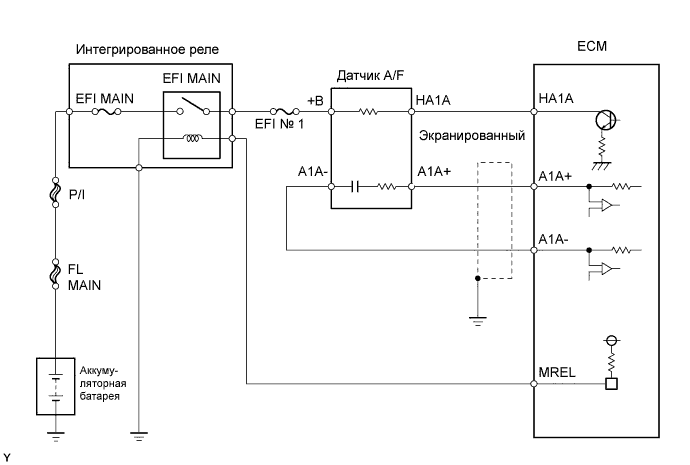
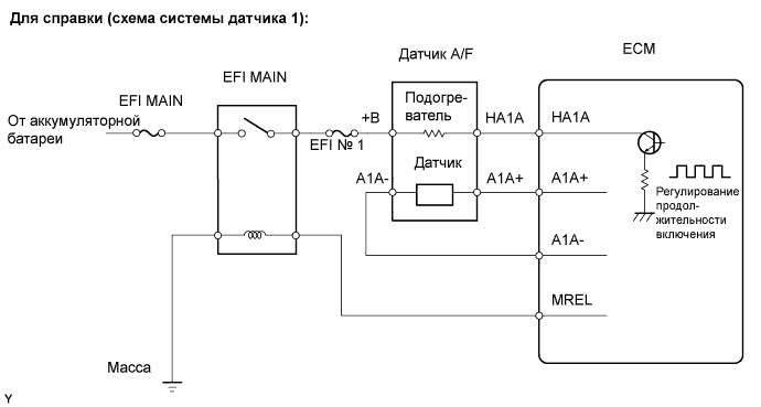
P2A00. Схема соединений
P2A00. Последовательность проверки
УКАЗАНИЕ:
Только при использовании портативного диагностического прибора:
Выполнив испытание "Control the Injection Volume for A/F Sensor" (управление объемом впрыска топлива для датчика состава топливовоздушной смеси) в режиме Active Test, можно определить неисправный участок. Испытание "Control the Injection Volume for A/F Sensor" может способствовать определению, какой из узлов неисправен: датчик состава топливовоздушной смеси (A/F), подогреваемый кислородный датчик (HO2) или какой-либо другой потенциально неисправный узел.
В следующих указаниях описывается порядок выполнения испытания "Control the Injection Volume for A/F Sensor" с помощью портативного диагностического прибора.
- (а) Подсоедините портативный диагностический прибор к разъему DLC3.
- (b) Запустите двигатель и включите портативный диагностический прибор.
- (c) Прогрейте двигатель на 2500 об/мин в течение приблизительно 90 секунд.
- (d) На портативном диагностическом приборе войдите в следующие меню: Powertrain / Engine and ECT / Active Test / Control the Injection Volume for A/F Sensor.
- (e) Выполните испытание "Control the Injection Volume for A/F Sensor" при работе двигателя на холостом ходу (нажмите правую или левую кнопку для изменения объема впрыска топлива).
- (f) Осуществите контроль выходного напряжения датчиков A/F и HO2 (AFS B1 S1 and O2S B1 S2), отображаемого на дисплее диагностического прибора.
УКАЗАНИЕ:
- Во время испытания "Control the Injection Volume for A/F Sensor" объем впрыска топлива снижается на 12,5% или увеличивается на 25%.
- Каждый датчик должен соответствующим образом реагировать на увеличение или уменьшение объема впрыска топлива.
Номинальное значение / Номинальный режим:
Информация на дисплее прибора
(Датчик)Объем впрыска топлива Состояние Напряжение AFS B1 S1
(A/F)+25% Обогащение Менее 3,0 -12,5% Обеднение Более 3,35 O2S B1 S2
(HO2)+25% Обогащение Более 0,5 -12,5% Обеднение Менее 0,4
ПРИМЕЧАНИЕ:
Задержка на выходе датчика A/F составляет несколько секунд, а задержка на выходе HO2 – приблизительно 20 секунд.
| Корпус | Датчик состава топливовоздушной смеси (датчик 1) Выходное напряжение |
Датчик HO2 (датчик 2) Выходное напряжение |
Наиболее вероятное место нахождения неисправности | ||
| 1 | Объем впрыска топлива +25% -12,5% |
 |
Объем впрыска топлива +25% -12,5% |
|
- |
| Выходное напряжение более 3,35 В менее 3,0 В |
 |
Выходное напряжение более 0,5 В менее 0,4 В |
 |
||
| 2 | Объем впрыска топлива +25% -12,5% |
|
Объем впрыска топлива +25% -12,5% |
|
|
| Выходное напряжение Реакция почти отсутствует |
 |
Выходное напряжение более 0,5 В менее 0,4 В |
|
||
| 3 | Объем впрыска топлива +25% -12,5% |
|
Объем впрыска топлива +25% -12,5% |
|
|
| Выходное напряжение более 3,35 В менее 3,0 В |
|
Выходное напряжение Реакция почти отсутствует |
|
||
| 4 | Объем впрыска топлива +25% -12,5% |
|
Объем впрыска топлива +25% -12,5% |
|
|
| Выходное напряжение Реакция почти отсутствует |
|
Выходное напряжение Реакция почти отсутствует |
|
||
- Описанное ниже испытание "Control the Injection Volume for A/F Sensor" дает механику возможность выполнить измерения и построить графики выходного напряжения для датчиков A/F и НО2.
- Для отображения графика на портативном диагностическом приборе войдите в следующие меню: Powertrain / Engine and ECT / Active Test / Control the Injection Volume for A/F Sensor / Enter / View / AFS B1 S1 и O2S B1 S2.
УКАЗАНИЕ:
- Код DTC P2A00 может также регистрироваться, если соотношение воздух-топливо постоянно обогащено или постоянно обеднено.
- Причиной появления низкого напряжения на выходе датчика A/F может быть обогащение топливовоздушной смеси. Проверьте, нет ли условий, приведших к работе двигателя на обогащенной смеси.
- Причиной появления высокого напряжения на выходе датчика A/F может быть обеднение топливовоздушной смеси. Проверьте, нет ли условий, приведших к работе двигателя на обедненной смеси.
- С помощью портативного диагностического прибора считайте фиксированные параметры. В этих параметрах отражается состояние двигателя на момент обнаружения неисправности. При поиске неисправностей фиксированные параметры позволяют определить, двигался ли автомобиль в момент возникновения неисправности или нет, был ли прогрет двигатель, какой была топливовоздушная смесь (обедненной или обогащенной) и пр.
| 1.ПРОВЕРЬТЕ, НЕ ОТОБРАЖАЮТСЯ ЛИ ДРУГИЕ DTC (ПОМИМО DTC P2A00) |
-
Подсоедините портативный диагностический прибор к DLC3.
-
Включите зажигание (IG).
-
Включите портативный диагностический прибор.
-
Выберите следующие элементы меню: Powertrain / Engine and ECT / DTC.
-
Считайте коды DTC.
Результат:
Индикация (отображаемые коды DTC) Следующий шаг P2A00 А P2A00 и другие DTC B
Если регистрируются какие-либо коды DTC, связанные с датчиком A/F (коды DTC для проводимости подогревателя датчика A/F или датчика A/F), сначала выполните поиск неисправностей для данных DTC.
|
|
||||
| А | |
| 2.ПРОВЕРЬТЕ ДАТЧИК СОСТАВА ТОПЛИВОВОЗДУШНОЙ СМЕСИ (СОПРОТИВЛЕНИЕ ПОДОГРЕВАТЕЛЯ) |
-
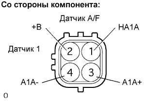
Отсоедините разъем В7 датчика A/F.
-
Измерьте сопротивление разъема датчика A/F.
Номинальное сопротивление:
Контакты для подключения диагностического прибора Заданные условия HA1A (1) - +B (2) 1,8-3,4 Ом при 20°C (68°F) HA1A (1) - A1A- (4) 10 кОм или более
-
Подсоедините разъем датчика A/F.
|
|
||||
| OK | |
| 3.ПРОВЕРЬТЕ ЖГУТ ПРОВОДОВ И РАЗЪЕМ (ECM - ДАТЧИК СООТНОШЕНИЯ ВОЗДУХ-ТОПЛИВО) |
-
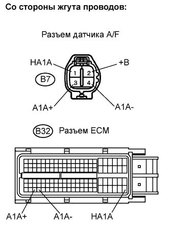
Отсоедините разъем В7 датчика A/F.
-
Включите зажигание (IG).
-
Измерьте напряжение между контактом +B разъема датчика A/F и массой.
Номинальное напряжение:
Контакты для подключения диагностического прибора Заданные условия +B (B7-2) - масса 9-14 В
-
Выключите зажигание.
-
Отсоедините разъем B32 ЕСМ.
-
Измерьте сопротивление.
Номинальное сопротивление (проверьте на обрыв):
Контакты для подключения диагностического прибора Заданные условия HA1A (B7-1) - HA1A (B32-109) Менее 1 Ом A1A+ (B7-3) - A1A+ (B32-112) Менее 1 Ом A1A- (B7-4) - A1A- (B32-113) Менее 1 Ом Номинальное сопротивление (проверьте на короткое замыкание):
Контакты для подключения диагностического прибора Заданные условия HA1A (B7-1) или HA1A (B32-109) - масса 10 кОм или более A1A+ (B7-3) или A1A+ (B32-112) - масса 10 кОм или более A1A- (B7-4) или A1A- (B32-113) - масса 10 кОм или более
-
Подсоедините разъем ECM.
-
Подсоедините разъем датчика A/F.
|
|
||||
| OK | |
| 4.ВЫПОЛНИТЕ ПОЕЗДКУ В ПРОВЕРОЧНОМ РЕЖИМЕ |
| ДАЛЕЕ | |
| 5.ПРОВЕРЬТЕ, ВОЗОБНОВЛЯЕТСЯ ЛИ ВЫВОД DTC (DTC P2A00) |
-
Подсоедините портативный диагностический прибор к DLC3.
-
Включите зажигание (IG) и включите портативный диагностический прибор.
-
Выберите следующие элементы меню: Powertrain / Engine and ECT / DTC.
-
Считайте коды DTC, ожидающие обработки.
Результат:
Индикация (отображаемые коды DTC) Следующий шаг P2A00 А Не выводится B
|
|
||||
| А | |
| 6.ЗАМЕНИТЕ ДАТЧИК СООТНОШЕНИЯ ВОЗДУХ-ТОПЛИВО |
| ДАЛЕЕ | |
| 7.ВЫПОЛНИТЕ ПОЕЗДКУ В ПРОВЕРОЧНОМ РЕЖИМЕ |
| ДАЛЕЕ | |
| 8.ПРОВЕРЬТЕ, ВОЗОБНОВЛЯЕТСЯ ЛИ ВЫВОД DTC (DTC P2A00) |
-
Подсоедините портативный диагностический прибор к DLC3.
-
Включите зажигание (IG) и включите портативный диагностический прибор.
-
Выберите следующие элементы меню: Powertrain / Engine and ECT / DTC.
-
Считайте коды DTC, ожидающие обработки.
Результат:
Индикация (отображаемые коды DTC) Следующий шаг Не выводится А P2A00 B
|
|
||||
| А | |
|