Components Crankshaft position sensor 2AD-FHV
Removal Crankshaft position sensor 2AD-FHV
Inspection Crankshaft position sensor 2AD-FHV
Installation Crankshaft position sensor 2AD-FHV
Crankshaft position sensor 2AD-FHV
Components
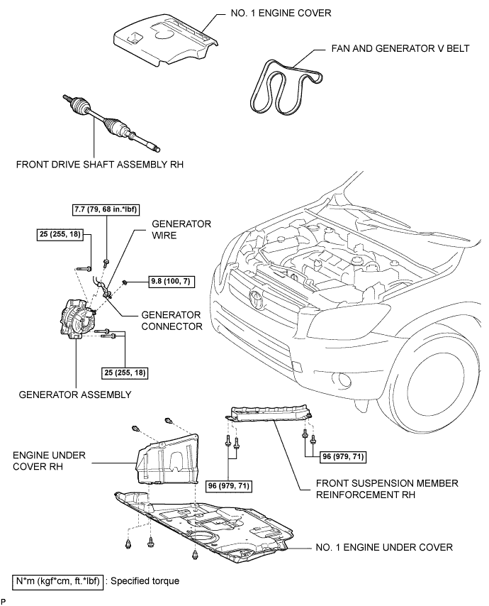
Crankshaft position sensor 2AD-FHV Components
Removal
CAUTION:
Wait at least 90 seconds after disconnecting the cable from the negative (-) battery terminal to prevent airbag and seat belt pretensioner activation.
-
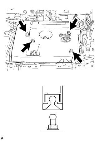
Detach the 4 clips and remove the engine cover.
-
Remove the 4 bolts, 12 clips and engine under cover.
-
Remove the 2 clips and engine under cover.
-
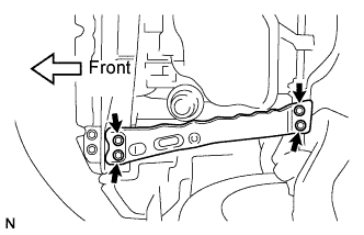
Remove the 4 bolts and reinforcement.
-
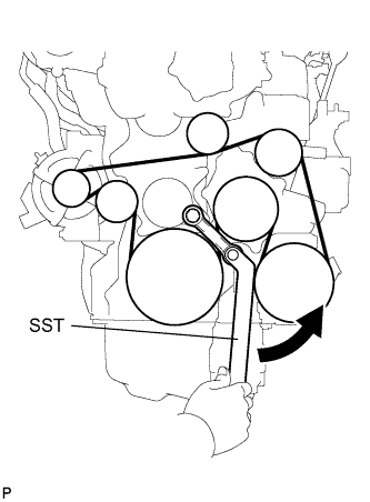
Using SST and 22 mm wrench, rotate the tensioner pulley counterclockwise to loosen the belt tension. Then remove the V-ribbed belt.
SST:
09216-42010
NOTICE:
Make sure SST is installed as shown in the illustration. If not, SST and/or the V-ribbed belt may not be able to be removed.
-
Remove the front drive shaft.
-
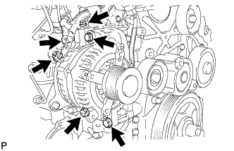
Disconnect the generator connector.
-
Remove the terminal cap.
-
Remove the nut and bolt, and disconnect the generator wire.
-
Remove the 3 bolts and generator.
-
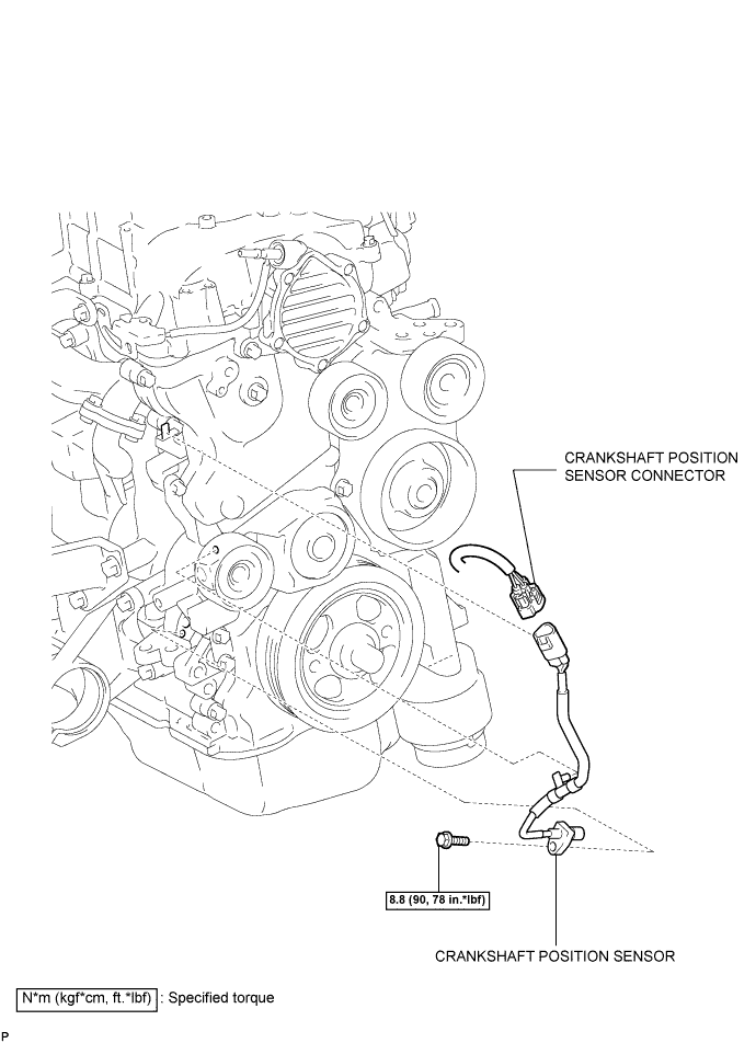
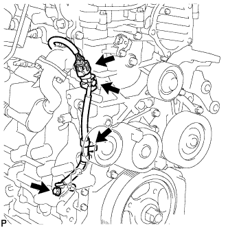
Disconnect the sensor connector.
-
Disconnect the sensor connector from the bracket.
-
Disconnect the sensor wire harness clamp.
-
Remove the bolt and sensor.
Crankshaft position sensor 2AD-FHV
Inspection
-
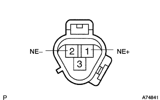
Measure the resistance between the terminals.
Standard resistance:
Temperature Specified Condition Cold 835 to 1,400 ? Hot 1,060 to 1,645 ? NOTICE:
In the table above, the terms "Cold" and "Hot" refer to the temperature of the coils. "Cold" means approximately -10 to 50°C (14 to 122°F). "Hot" means approximately 50 to 100°C (122 to 212°F).
If the resistance is not as specified, replace the sensor.
Crankshaft position sensor 2AD-FHV
Installation
-
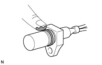
Apply a light coat of engine oil to the O-ring of the sensor.
-
Install the sensor with the bolt.
Torque:
8.8 Н*м{ 90 кгс*см , 78 фунт-сила-дюймов }
-
Connect the sensor wire harness clamp.
-
Connect the sensor connector to the bracket.
-
Connect the sensor connector.
-
Install the generator with the 3 bolts.
Момент затяжки:
25 Н*м{ 255 кгс*см , 18 фунт-сила-футов }
NOTICE:
Be careful that the wire harness of the crankshaft position sensor does not get caught between the cylinder block and generator when installing the generator.
-
Connect the generator wire with the nut and bolt.
Torque:
9.8 Н*м{ 100 кгс*см , 87 фунт-сила-дюймов } for nut
7.7 Н*м{ 79 кгс*см , 68 фунт-сила-дюймов } for bolt
-
Install the terminal cap.
-
Connect the generator connector.
-
Install the front drive shaft.
-
Using SST and 22 mm wrench, rotate the tensioner pulley counterclockwise, and then install the V-ribbed belt.
SST:
09216-42010
NOTICE:
- Make sure that the V-ribbed belt is set properly at each pulley.
- Make sure SST is installed as shown in the illustration. If not, SST and/or the V-ribbed belt may not be able to be removed.
-
Install the reinforcement with the 4 bolts.
Torque:
95 Н*м{ 969 кгс*см , 70 фунт-сила-футов }
-
Install the engine under cover with the 2 clips.
-
Install the engine under cover with the 12 clips and 4 bolts.
-
Attach the 4 clips to install the engine cover.