INSTALL DRIVE PLATE AND RING GEAR SUB-ASSEMBLY (for Automatic Transaxle)
INSPECT AND ADJUST CLUTCH COVER ASSEMBLY (for Manual Transaxle)
INSTALL AUTOMATIC TRANSAXLE ASSEMBLY (for Automatic Transaxle)
Rear Crankshaft Oil Seal (For Hatchback) -- Installation |
| 1. INSTALL REAR ENGINE OIL SEAL |
Apply MP grease to the lip of a new oil seal.
- NOTICE:
- Keep the lip free of foreign matter.
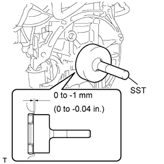
Using SST and hammer, tap in the oil seal until its surface is flush with the cylinder block and oil pan.
- SST
- 09223-56010
- CAUTION:
- Do not tap the oil seal at an angle.
- Wipe off extra grease from the crankshaft.
 |
| 2. INSTALL DRIVE PLATE AND RING GEAR SUB-ASSEMBLY (for Automatic Transaxle) |
Hold the crankshaft with SST.
- SST
- 09960-10010(09962-01000,09963-01000)
Clean the 6 bolts and their holes.
Apply adhesive to the 2 or 3 end threads of the bolt.
Text in Illustration *1 Adhesive - NOTICE:
- Do not start the engine for at least 1 hour after installation.
- Adhesive:
- Toyota Genuine Adhesive 1324, Three Bond 1324 or equivalent
 |
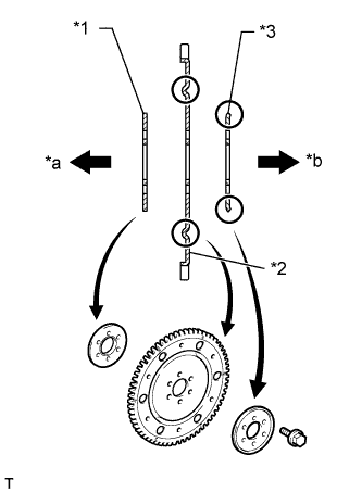
Install the rear drive plate spacer, drive plate and ring gear sub-assembly, and front drive plate spacer with the 6 bolts.
Text in Illustration *1 Front Drive Plate Spacer *2 Drive Plate and Ring Gear *3 Rear Drive Plate Spacer *a Engine Side *b Transaxle Side
 |
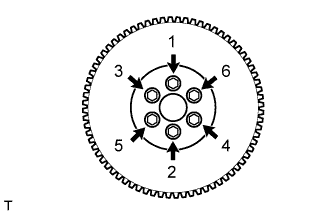
Install and uniformly tighten the 6 bolts in several steps, in the sequence shown in the illustration.
- Torque:
- 88 N*m{897 kgf*cm, 65 ft.*lbf}
 |
| 3. INSTALL FLYWHEEL SUB-ASSEMBLY (for Manual Transaxle) |
Hold the crankshaft with SST.
- SST
- 09960-10010(09962-01000,09963-01000)
Clean the 6 bolts and their holes.
Apply adhesive to the 2 or 3 end threads of bolt.
Text in Illustration *1 Adhesive - NOTICE:
- Do not start the engine for at least 1 hour after installation.
- Adhesive:
- Toyota Genuine Adhesive 1324, Three Bond 1324 or equivalent
|
Install the flywheel with the 6 bolts.
Install the flywheel with the 6 bolts in the order shown in the illustration.
- Torque:
- 49 N*m{500 kgf*cm, 38 ft.*lbf}
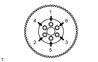 |
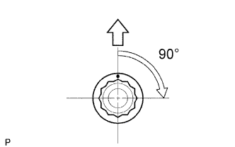
Mark paint marks on the bolt heads on the engine upper side.
Tighten the bolts 90° in the sequence order shown in the illustration.
 |
| 4. INSTALL CLUTCH DISC ASSEMBLY (for Manual Transaxle) |
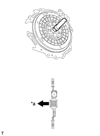
Insert SST into the clutch disc assembly, then insert them both into the flywheel sub-assembly.
Text in Illustration *a Flywheel Side - SST
- 09301-00210
- NOTICE:
- Insert the clutch disc assembly in the correct direction.
 |
| 5. INSTALL CLUTCH COVER ASSEMBLY (for Manual Transaxle) |
Align the matchmark on the clutch cover assembly with that on the flywheel sub-assembly.
Text in Illustration *a Temporally *b matchmarks
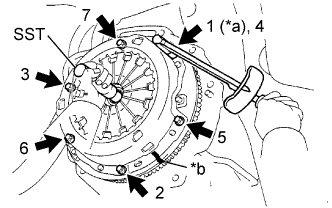 |
Following the procedures shown in the illustration, tighten the 6 bolts in order, starting with the bolt located near the knock pin at the top.
- Torque:
- 19 N*m{195 kgf*cm, 14 ft.*lbf}
- HINT:
- Following the order in the illustration, tighten the blots evenly one at a time.
- Move SST up and down, right and left lightly after checking that the disc is in the center, and tighten the bolts.
- SST
- 09301-00210
| 6. INSPECT AND ADJUST CLUTCH COVER ASSEMBLY (for Manual Transaxle) |
 |
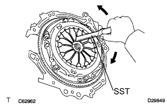
Using a dial indicator with a roller instrument, check the diaphragm spring tip alignment.
- Maximum non-alignment:
- 0.5 mm (0.020 in.)
If the alignment is not as specified, using SST, adjust the diaphragm spring tip alignment.
- SST
- 09333-00013
 |
| 7. INSTALL MANUAL TRANSAXLE ASSEMBLY (for Manual Transaxle) |
| 8. INSTALL AUTOMATIC TRANSAXLE ASSEMBLY (for Automatic Transaxle) |
| 9. INSPECT FOR OIL LEAK |