Dtc B279A Theft Deterrent System Communication Line High Fixation
DESCRIPTION
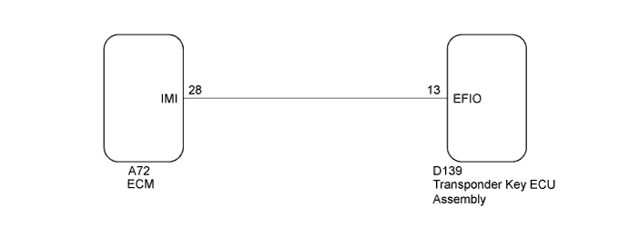
WIRING DIAGRAM
INSPECTION PROCEDURE
CLEAR DTC
CHECK FOR DTC
CHECK CONNECTION OF CONNECTOR
CHECK HARNESS AND CONNECTOR (TRANSPONDER KEY ECU ASSEMBLY - ECM)
REPLACE TRANSPONDER KEY ECU ASSEMBLY
REGISTER KEY
REGISTER ECU COMMUNICATION ID
CHECK WHETHER ENGINE STARTS
DTC B279A Theft Deterrent System Communication Line High Fixation |
DESCRIPTION
When the communication line (IMI - EFIO) between the ECM and transponder key ECU assembly is stuck on HI output, the ECM stores this DTC.DTC Code
| DTC Detection Condition
| Trouble Area
| DTC Output Confirmation Operation
|
B279A
| The communication line (IMI - EFIO) between the ECM and transponder key ECU assembly is stuck on HI output (1 trip detection logic*).
| - Harness or connector
- Transponder key ECU assembly
- ECM
| Turn the ignition switch to ON and wait 6 seconds.
|
- *: Only output while a malfunction is present.
Vehicle Condition and Fail-safe Operation when Malfunction DetectedVehicle Condition when Malfunction Detected
| Fail-safe Operation when Malfunction Detected
|
Engine cannot be started (initial ignition occurs and engine cranks, then ignition stops)
| Engine cannot be started
|
Related Data List and Active TestDTC Code
| Data List and Active Test
|
B279A
| -
|
WIRING DIAGRAM
INSPECTION PROCEDURE
- NOTICE:
- When replacing the transponder key ECU assembly, refer to the Registration (YARIS_NCP93 RM00000120Y021X.html).
- When replacing the ECM, refer to the INITIALIZATION (YARIS_NCP93 RM00000482M008X.html).
- After performing repairs, perform the operation that fulfills the DTC output confirmation operation, and then confirm that no DTCs are output again.
Clear the DTCs (YARIS_NCP93 RM000001TCQ01OX.html).
Check for DTCs (YARIS_NCP93 RM000001TCQ01OX.html).
- HINT:
- Before checking for DTCs, perform the "DTC Output Confirmation Operation" procedure.
- OK:
- DTC B279A is not output.
| 3.CHECK CONNECTION OF CONNECTOR |
Check that the connectors are properly connected to the ECM and transponder key amplifier assembly.
- OK:
- Connectors are properly connected.
| | CONNECT CONNECTORS PROPERLY |
|
|
| 4.CHECK HARNESS AND CONNECTOR (TRANSPONDER KEY ECU ASSEMBLY - ECM) |
Disconnect the D139 transponder key ECU assembly connector.
Disconnect the A72 ECM connector.
Measure the resistance according to the value(s) in the table below.
- Standard Resistance:
Tester Connection
| Condition
| Specified Condition
|
D139-13 (EFIO) - A72-28 (IMI)
| Always
| Below 1 Ω
|
D139-13 (EFIO) - Body ground
| Always
| 10 kΩ or higher
|
| | REPAIR OR REPLACE HARNESS OR CONNECTOR |
|
|
| 5.REPLACE TRANSPONDER KEY ECU ASSEMBLY |
Replace the transponder key ECU assembly with a new one (YARIS_NCP93 RM000004E7M008X.html).
Register the key (YARIS_NCP93 RM00000120Y021X.html).
| 7.REGISTER ECU COMMUNICATION ID |
Register the ECU communication ID (YARIS_NCP93 RM00000120Y021X.html).
| 8.CHECK WHETHER ENGINE STARTS |
Check that the engine starts with the key.
- OK:
- Engine starts normally.
| OK |
|
|
|
| END (TRANSPONDER KEY ECU ASSEMBLY WAS DEFECTIVE) |
|