Vehicle Stability Control System (For Sedan) Trac Off Indicator Light Remains On
DESCRIPTION
WIRING DIAGRAM
INSPECTION PROCEDURE
CHECK CAN COMMUNICATION SYSTEM
CHECK IF SKID CONTROL ECU CONNECTOR IS SECURELY CONNECTED
INSPECT BATTERY
READ VALUE USING TECHSTREAM (VSC OFF SWITCH)
REPLACE COMBINATION METER ASSEMBLY
CHECK THAT TRAC OFF INDICATOR IS ILLUMINATED
INSPECT VSC OFF SWITCH
CHECK HARNESS AND CONNECTOR (SKID CONTROL ECU - VSC OFF SWITCH)
VEHICLE STABILITY CONTROL SYSTEM (for Sedan) - TRAC OFF Indicator Light Remains ON |
DESCRIPTION
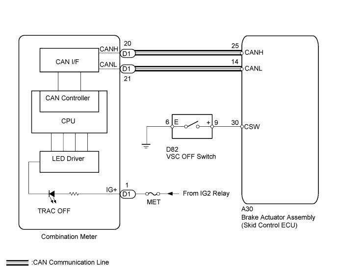
The skid control ECU is connected to the combination meter via CAN communication.Pressing the VSC OFF switch turns off traction control and pressing and holding this switch turns off traction and VSC controls. If TRAC control is turned off, the TRAC OFF indicator light will come on.
WIRING DIAGRAM
INSPECTION PROCEDURE
- NOTICE:
- When replacing the brake actuator assembly, perform zero point calibration and store system information (YARIS_NCP93 RM000000XHR06QX.html).
| 1.CHECK CAN COMMUNICATION SYSTEM |
Check if a CAN communication system DTC is output (YARIS_NCP93 RM000001D3E00OX.html).
ResultResult
| Proceed to
|
DTC is not output
| A
|
DTC is output
| B
|
| 2.CHECK IF SKID CONTROL ECU CONNECTOR IS SECURELY CONNECTED |
Check if the skid control ECU connector is securely connected.
- OK:
- The connector is securely connected.
| | CONNECT CONNECTOR TO ECU CORRECTLY |
|
|
Check the battery voltage.
- Standard voltage:
- 11 to 14 V
| 4.READ VALUE USING TECHSTREAM (VSC OFF SWITCH) |
Connect the Techstream to the DLC3.
Turn the engine switch to ON.
Select the Data List on the Techstream (YARIS_NCP93 RM000000XHW09EX.html).
ABS/VSC/TRACTester Display
| Measurement Item/Range
| Normal Condition
| Diagnostic Note
|
TRAC/VSC Off Mode
| TRAC/VSC off mode / Normal, TRAC OFF or VSC OFF
| Normal: Normal mode
TRAC OFF: TRAC OFF mode
VSC OFF: VSC OFF mode
| -
|
Using the Techstream, check the switch condition on the Techstream changes according to VSC OFF switch operation.
- OK:
- The Techstream display changes according to VSC OFF switch operation.
| 5.REPLACE COMBINATION METER ASSEMBLY |
Turn the ignition switch off.
Replace the combination meter (YARIS_NCP93 RM000000IN001JX.html).
| 6.CHECK THAT TRAC OFF INDICATOR IS ILLUMINATED |
Check if the TRAC OFF indicator is illuminated when the ignition switch is turned to ON.
- OK:
- TRAC OFF indicator should be illuminated.
- HINT:
- When the ignition switch is turned to ON, TRAC OFF indicator lights come on for approximately 3 seconds. This signal comes from the skid control ECU via CAN communication.
Turn the ignition switch off.
Disconnect the VSC OFF switch connector.
Measure the resistance according to the value(s) in the table below.
- Standard Resistance:
Tester Connection
| Switch Condition
| Specified Condition
|
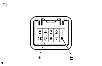
6 (E) - 9 (+)
| Switch is pushed in
| Below 1 Ω
|
6 (E) - 9 (+)
| Switch is not pushed in
| 10 kΩ or higher
|
Text in Illustration*1
| Component without harness connected
(VSC OFF Switch)
|
| 8.CHECK HARNESS AND CONNECTOR (SKID CONTROL ECU - VSC OFF SWITCH) |
Connect the skid control ECU connector.
Measure the resistance according to the value(s) in the table below.
- Standard Resistance:
Tester Connection
| Condition
| Specified Condition
|
A30-30 (CSW) - D82-9 (+)
| Always
| Below 1 Ω
|
A30-30 (CSW) - Body ground
| Always
| 10 kΩ or higher
|
D82-6 (E) - Body ground
| Always
| Below 1 Ω
|
- HINT:
- If troubleshooting has been carried out according to Problem Symptoms Table, refer back to the table and proceed to the next step (YARIS_NCP93 RM000000XHN0AXX.html).
| | REPAIR OR REPLACE HARNESS OR CONNECTOR |
|
|