Engine (For Hatchback) -- On-Vehicle Inspection |
| 1. INSPECT COOLANT |
Remove the water filler cap sub-assembly.
- CAUTION:
- To avoid the danger of being burned, do not remove the water filler cap sub-assembly while the engine and radiator assembly are still hot.
- Thermal expansion will cause hot engine coolant and steam to blow out from the radiator assembly.
Check for excessive deposits of rust or scale around the water filler cap sub-assembly and radiator filler hole. The engine coolant should be free of oil.
If excessively dirty, replace the engine coolant.
Reinstall the water filler cap sub-assembly.
| 2. INSPECT ENGINE OIL |
Check the oil for deterioration, entry of water, discoloring or thinning.
If the quality is visibly poor, replace the oil.
| 3. INSPECT BATTERY |
Check the battery for damage and deformation. If severe damage, deformation or leakage is found, replace the battery.
Check the volume of electrolyte in each cell.
For batteries that are maintenance-free:
- If the electrolyte volume is below the lower line, replace the battery.
- If the electrolyte volume is above the lower line, check the battery voltage when cranking the engine.
- If the voltage is less than 9.6 V, recharge or replace the battery.
- HINT:
- Before checking the battery voltage, turn off all the electrical systems (headlights, blower motor, etc.).
- If the electrolyte volume is below the lower line, replace the battery.
For batteries that are not maintenance-free:
- If the electrolyte volume is below the lower line, add distilled water to each cell. Then, recharge the battery and check the specific gravity of the electrolyte.
- Standard specific gravity:
- 1.25 to 1.29 at 20 °C ( 68 °F)
- HINT:
- Before checking the battery voltage, turn off all the electrical systems (headlights, blower motor, rear defogger, etc.).
- If the electrolyte volume is below the lower line, add distilled water to each cell. Then, recharge the battery and check the specific gravity of the electrolyte.
| 4. INSPECT AIR CLEANER FILTER ELEMENT SUB-ASSEMBLY |
Remove air cleaner cap sub-assembly (YARIS_NCP93 RM000003VHR00IX_01_0003.html).
Remove the air cleaner filter element sub-assembly.
Visually check that the air cleaner filter is not excessively damaged or oily. If necessary, replace the air cleaner filter.
- HINT:
- If there is any dirt or a blockage in the air cleaner filter element, clean it with compressed air.
- If any dirt or a blockage remains even after cleaning the air cleaner filter element with compressed air, replace it.
Install the air cleaner filter element sub-assembly.
Install the air cleaner cap sub-assembly (YARIS_NCP93 RM000003VHO00IX.html).
| 5. INSPECT FAN AND GENERATOR V BELT |
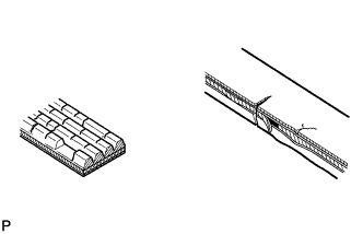 |
Check the fan and generator V belt for wear, cracks or other signs of damage.
If any of the following defects is found, replace the fan and generator V belt.- The fan and generator V belt is cracked.
- The fan and generator V belt is worn out to the extent that the cords are exposed.
- The fan and generator V belt has chunks missing from the ribs.
- The fan and generator V belt is cracked.
Check that the fan and generator V belt fits properly in the ribbed grooves.
Text in Illustration *a Correct *b Incorrect - HINT:
- Check with your hand to confirm that the fan and generator V belt has not slipped out of the grooves on the bottom of the pulley. If it has slipped out, replace the fan and generator V belt. Install a new fan and generator V belt correctly.
 |
Inspect the V belt deflection and tension.
Text in Illustration *A w/o Air Conditioner *B w/ Air Conditioner - Deflection:
Item Specified Condition New belt 8.0 to 9.0 mm (0.31 to 0.35 in) Used belt 12.5 to 13.5 mm (0.49 to 0.53 in)
- Tension:
Item Specified Condition New belt 700 to 800 N (71 to 82 kg, 157 to 180 lb) Used belt 300 to 400 N (31 to 41 kg, 67 to 90 lb)
- HINT:
- When inspecting the V belt deflection, apply 98 N (10 kgf) tensile force to it.
- Perform the V belt inspection and adjustment while the engine is cold.
- V-ribbed belt tension and deflection should be checked immediately after installation of a new belt, and after cranking the engine when inspecting a used belt.
- Check the V belt deflection at the point between the specified pulleys where the deflection is greatest.
- When installing a new belt, set its tension to the intermediate value of the specification.
- When inspecting a belt which has been used for over 5 minutes, apply the Used Belt specifications.
- When reinstalling a belt which has been used for over 5 minutes, adjust its deflection and tension to the intermediate values of each Used Belt specification.
- V-ribbed belt tension and deflection should be checked after 2 revolutions of engine cranking.
- When using a belt tension gauge, confirm its accuracy by using a master gauge first.
 |
| 6. INSPECT SPARK PLUG |
- NOTICE:
- Do not use a wire brush for cleaning.
- Do not attempt to adjust the electrode gap of a used spark plug.
Check the electrode.
Text in Illustration *1 Body Ground Measure the insulation resistance.
- Standard Resistance:
- 10 MΩ or more
- HINT:
- If the result is not as specified, clean the spark plug with a spark plug cleaner and measure the resistance again.
- If a megohmmeter is not available, perform the following simple inspection instead.
 |
Alternative inspection method:
Quickly accelerate the engine to 4000 rpm 5 times.
- NOTICE:
- When DTC P0300 (Random / Multiple Cylinder Misfire Detected) or related DTCs are output, do not perform this step.
Remove the spark plug.
Visually check the spark plug.
If the electrode is dry, the spark plug is functioning properly. If the electrode is damp, proceed to the next step.

Check the spark plug for any damage to its thread and insulator.
If there is any damage, replace the spark plug.- Recommended Spark Plug:
Manufacturer Product DENSO FK16HR11
Clean the spark plug.
If the electrode has traces of wet carbon, clean the electrode with a spark plug cleaner and then dry with compressed air.- Air Pressure:
- 588 kPa (6 kgf/cm2, 85 psi)
- Duration:
- 20 seconds or less
- HINT:
- Only use the spark plug cleaner when the electrode is free of oil. If the electrode has traces of oil, use gasoline to clean off the oil before using the spark plug cleaner.
| 7. INSPECT IGNITION TIMING |
When using an Techstream:
Warm up and stop the engine.
Connect the Techstream to the DLC3.
Turn the ignition switch to ON.
Turn the Techstream on.
Start the engine.
Enter the following menus: Powertrain / Engine and ECT / Active Test /Connect the TC and TE1 / ON.
- HINT:
- Refer to the Techstream operator's manual for further details.
Inspect the ignition timing during idling.
- Standard ignition timing:
Transaxle Ignition Timing Manual Transaxle 8 to 12 degrees BTDC Automatic Transaxle
- NOTICE:
- Check the ignition timing with the cooling fans off..
- Turn off all electrical systems and the A/C.
- When checking the ignition timing, the transaxle should be in neutral or park.
- HINT:
- Refer to the Techstream operator's manual for further details.
Select the following menu items: Connect the TC and TE1 / OFF.
Turn the ignition switch off.
Disconnect the Techstream from the DLC3.
When not using an Techstream:
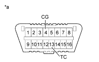
Using SST, connect terminals 13 (TC) and 4 (CG) of the DLC3.
Text in Illustration *a Front view of DLC3 - SST
- 09843-18040
- NOTICE:
- Be sure to connect the terminals correctly. Failure to do this can damage the engine.
- Check the ignition timing with the cooling fans off.
- Turn off all electrical systems and the A/C.
- When checking the ignition timing, the transaxle should be in neutral or park.
Remove the No. 2 cylinder head cover (YARIS_NCP93 RM000003VHK00GX_01_0007.html).
Pull out the wire harness (brown) shown in the illustration.
- NOTICE:
- After checking, wrap the wire harness with tape.
Warm up and stop the engine.
Connect the clip of the timing light to the wire harness.
- NOTICE:
- Use a timing light that detects the first signal.
Start the engine.
Inspect the ignition timing during idling.
- Standard ignition timing:
Transaxle Ignition Timing Manual Transaxle 8 to 12 degrees BTDC Automatic Transaxle
- NOTICE:
- Turn all the electrical systems and the A/C off.
- Inspect the ignition timing with the cooling fan off.
- When checking the ignition timing, shift the transaxle to the neutral position.
Turn the ignition switch off.
Remove the timing light.
Install the No. 2 cylinder head cover (YARIS_NCP93 RM000003VHI00GX_01_0008.html).
Disconnect terminals 13 (TC) and 4 (CG) of the DLC3.

| 8. INSPECT ENGINE IDLING SPEED |
When using an Techstream:
Warm up and stop the engine.
Connect the Techstream to the DLC3.
Turn the ignition switch to ON and turn the Techstream on.
Start the engine.
Select the following menu items: Powertrain / Engine and ECT / Data List / Engine Speed.
- HINT:
- Refer to the Techstream operator's manual for further details.
Inspect the engine idling speed.
- Standard Idle Speed:
Transaxle Idling Speed Manual Transaxle 550 to 650 rpm Automatic Transaxle 650 to 750 rpm
- NOTICE:
- Turn all the electrical systems and the A/C off.
- Inspect the idling speed with the cooling fan off.
- When checking the idling speed, shift the transaxle to the neutral position or the parking position.
Turn the ignition switch off.
Disconnect the Techstream from the DLC3.
When not using an Techstream.
Warm up and stop the engine.
Install SST to terminals 13 (TC) and 4 (CG) of the DLC3.
Text in Illustration *a Front view of DLC3 - SST
- 09843-18040
- NOTICE:
- Examine the terminal numbers before connecting them. Connecting the wrong terminals can damage the engine.
Start the engine.
Inspect the engine idling speed.
- Standard Idle Speed:
Transaxle Idling Speed Manual Transaxle 600 to 700 rpm Automatic Transaxle 650 to 750 rpm
- NOTICE:
- Turn all the electrical systems and the A/C off.
- Inspect the idling speed with the cooling fan off.
- When checking the idling speed, shift the transaxle to the neutral position or the parking position.
Turn the ignition switch off.
Disconnect the tachometer.
Remove SST from terminals 13 (TC) and 4 (CG) of the DLC3.
| 9. INSPECT VALVE CLEARANCE |
Check for noise and vibration.
Check for valve noise or a rough idle.
Judge whether valve clearance needs to be adjustmented.
If the valve noise is too loud or the idle is rough, inspect the valve clearance (YARIS_NCP93 RM000001DCK013X.html).
| 10. INSPECT COMPRESSION |
Warm up and stop the engine.
Remove the No. 2 cylinder head cover (YARIS_NCP93 RM000003VHK00GX_01_0007.html).
Remove the 4 ignition coils (YARIS_NCP93 RM000002YO404IX_01_0003.html ).
Remove the 4 spark plugs (YARIS_NCP93 RM000002YO404IX_01_0004.html).
Disconnect the 4 fuel injector connectors.
Inspect the cylinder compression pressure.
Insert a compression gauge into the spark plug hole.
Fully open the throttle.
While cranking the engine, measure the compression pressure.
- Compression:
- 980 kPa (10.0 kgf/cm2, 142 psi)
- Minimum pressure:
- 784 kPa (8.0 kgf/cm2, 114 psi)
- Difference between each cylinder:
- 98 kPa (1.0 kgf/cm2, 14 psi) or less
- NOTICE:
- Use a fully-charged battery so the engine speed can be increased to 250 rpm or more.
- Inspect the other cylinders in the same way.
- Measure the compression in as short a time as possible.
If the cylinder compression is low, pour a light coat of engine oil into the cylinder through the spark plug hole, then inspect it again.
- HINT:
- If adding oil increases the compression, the piston rings and/or cylinder bore may be worn or damaged.
- If the pressure stays low, the valve may be stuck or seated improperly, or there may be leakage from the gasket.
 |
Connect the 4 fuel injector connectors.
Install the 4 spark plugs (YARIS_NCP93 RM000002YO204IX_01_0001.html).
Install the 4 ignition coils (YARIS_NCP93 RM000002YO204IX_01_0002.html).
Install the No. 2 cylinder head cover (YARIS_NCP93 RM000003VHI00GX_01_0008.html).
Clear the DTC (YARIS_NCP93 RM000000PDK0T5X.html).
| 11. INSPECT CO/HC |
Start the engine.
Run the engine at 2500 rpm for approximately 180 seconds.
Insert the CO/HC meter testing probe at least 40 cm (1.3 ft) into the tailpipe while idling.
Check the CO/HC concentration during idling and when running at 2500 rpm.
- HINT:
- When doing the 2 mode (with the engine idling/running at 2500 rpm) test, the measuring procedures are determined by applicable local regulations.
Check the air fuel ratio sensor operation (YARIS_NCP93 RM000000SXS05AX.html).
Check the heated oxygen sensor operation (YARIS_NCP93 RM000000SXS05AX.html).
See the table below for possible causes, then inspect the applicable parts and repair them if necessary.
CO HC Problems Possible Causes Normal High Rough idling - Faulty ignition:
- Incorrect timing
- Fouled, shorted or improperly gapped plugs
- Incorrect valve clearance
- Leakage from intake and exhaust valves
- Leakage from cylinders
Low High Rough idling
(Fluctuating HC reading)- Vacuum leaks:
- PCV hoses
- Intake manifold
- Throttle body
- Brake booster line
- Lean mixture causing misfire
High High Rough idling
(Black smoke from exhaust)- Restricted air cleaner filter element
- Plugged PCV valve
- Faulty EFI systems:
- Faulty pressure regulator
- Faulty engine coolant temperature sensor
- Faulty mass air flow meter
- Faulty ECM
- Faulty injectors
- Throttle body
- Faulty ignition: