Valve Clearance (For Hatchback) -- Adjustment |
- NOTICE:
- After turning the ignition switch off, waiting time may be required before disconnecting the cable from the battery terminal. Therefore, make sure to read the disconnecting the cable from the battery terminal notice before proceeding with work (YARIS_NCP93 RM00000482L007X.html).
| 1. DISCONNECT CABLE FROM NEGATIVE BATTERY TERMINAL |
| 2. REMOVE ENGINE UNDER COVER RH |
| 3. REMOVE NO. 2 CYLINDER HEAD COVER |
Remove the 4 nuts and No. 2 cylinder head cover.
 |
| 4. REMOVE NO. 1 IGNITION COIL |
Disconnect the 4 No. 1 ignition coil connectors.
 |
Remove the 4 bolts and the 4 No. 1 ignition coils.
 |
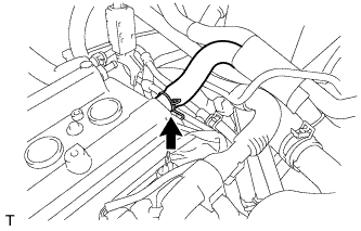
| 5. DISCONNECT VENTILATION HOSE |
 |
Disconnect the ventilation hose.
| 6. DISCONNECT FUEL VAPOR FEED HOSE ASSEMBLY |
 |
Disconnect the fuel vapor feed hose assembly.
| 7. REMOVE CYLINDER HEAD COVER SUB-ASSEMBLY |
Disconnect the fuel injector connectors.
 |
Disconnect the connector and 4 wire harness clamps shown in the illustration and disconnect the engine wire harness.
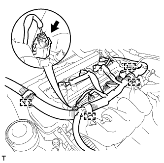 |
Remove the bolt and the wire harness bracket.
 |
Remove the 9 bolts, 2 nuts and 2 seal washers and then remove the cylinder head cover sub-assembly.
 |
| 8. INSPECT VALVE CLEARANCE |
- HINT:
- Inspect the valve clearance when the engine is cold.
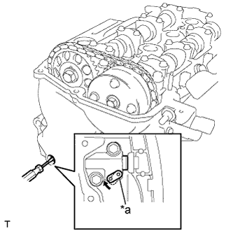
Set the No. 1 cylinder to TDC/compression.
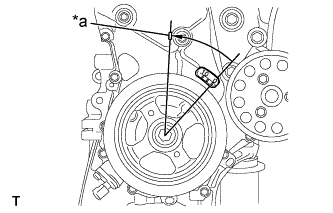
Turn the crankshaft damper and align its timing notch with the timing mark "0" of the oil pump.
Text in Illustration *a Timing Notch Check that both timing marks on the camshaft timing sprocket and camshaft timing gear are facing upward, as shown in the illustration.
Text in Illustration *a Timing Marks - HINT:
- If not, turn the crankshaft 1 complete revolution (360°) and align the marks as above.


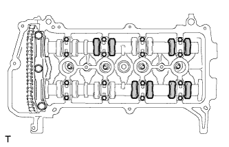
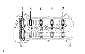
Check the valves indicated in the illustration.
Using a feeler gauge, measure the clearance between the valve lifter and camshaft.
- Valve clearance (cold):
- for intake:
- 0.15 to 0.25 mm (0.006 to 0.010 in.)
- for exhaust:
- 0.25 to 0.35 mm (0.010 to 0.014 in.)
Record any out-of-specification valve clearance measurements. They will be used later to determine the required replacement adjusting shim.
 |
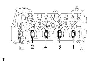
Turn the crankshaft 1 complete revolution (360°) and align its timing notch with the timing mark "0" of the oil pump.
Check the valves indicated in the illustration.
Using a feeler gauge, measure the clearance between the valve lifter and camshaft.
- Valve clearance (cold):
- for intake:
- 0.15 to 0.25 mm (0.006 to 0.010 in.)
- for exhaust:
- 0.25 to 0.35 mm (0.010 to 0.014 in.)
Record any out-of-specification valve clearance measurements. They will be used later to determine the required replacement adjusting shim.
 |
| 9. ADJUST VALVE CLEARANCE |
 |
| *a | Matchmark |
- NOTICE:
- When rotating the camshaft with the timing chain removed, rotate the crankshaft damper counterclockwise 40° from the TDC and align its timing notch with the matchmark of the timing chain cover to prevent the pistons from coming into contact with the valves.
Remove the fan and generator V belt (YARIS_NCP93 RM000001DCJ01CX_01_0002.html).
Remove the engine mounting insulator sub-assembly RH (YARIS_NCP93 RM000001DDZ00UX_01_0037.html).
Set the No. 1 cylinder to TDC/compression.
Turn the crankshaft damper and align its timing notch with the timing mark "0" of the oil pump.
Text in Illustration *a Timing Notch Check that both timing marks on the camshaft timing sprocket and camshaft timing gear are facing upward, as shown in the illustration.
Text in Illustration *a Timing Marks - HINT:
- If not, turn the crankshaft 1 complete revolution (360°) and align the marks as above.


Place paint marks on the chain in the places where the timing marks of the camshaft timing sprocket and the camshaft timing gear are located.
Text in Illustration *a Paint Marks *b Timing Marks
 |
Using an 8 mm hexagon wrench, remove the screw plug.
 |
Insert a screwdriver into the service hole in the chain tensioner to pull the stopper plate of the chain tensioner upward.
Text in Illustration *a Stopper Plate
 |
Using a wrench, rotate camshaft No. 2 clockwise to push in the plunger of the chain tensioner.
Text in Illustration *a Plunger
 |
Remove the screwdriver from the service hole, then align the hole in the stopper plate with the service hole and insert a 3 mm (0.12 in.) diameter bar into the holes to hold the stopper plate.
- HINT:
- Fix the stopper plate using the bar while rotating the camshaft right and left slightly.
- Hold the bar with tape so that the bar does not come off.
 |
Using a wrench, hold the hexagonal lobe of camshaft No. 2 and remove the flange bolt.
 |
Using several steps, loosen and remove the 11 bearing cap bolts uniformly in the sequence shown in the illustration, then remove camshaft bearing cap No. 1 and camshaft bearing cap No. 2.
- NOTICE:
- Loosen each bolt uniformly while keeping the camshaft level.
 |
Remove the flange bolt and the camshaft timing sprocket.
 |
Remove No. 2 camshaft.
 |
Using several steps, loosen and remove the 8 bearing cap bolts uniformly in the sequence shown in the illustration, then remove No. 2 camshaft bearing cap.
- NOTICE:
- Loosen each bolt uniformly while keeping the camshaft level.
 |
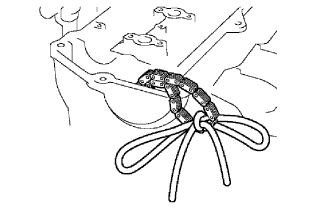
Hold the chain by hand and remove the camshaft and the camshaft timing gear assembly.
 |
Tie the chain with a piece of string as shown in the illustration.
 |
Remove the 16 valve lifters.
Using a micrometer, measure the thickness of the removed lifter.
 |
Calculate the thickness of a new lifter so that the valve clearance comes to within the specified values.
A Thickness of new lifter B Thickness of used lifter C Measured valve clearance - Valve clearance:
- Intake A = B + (C - 0.20 mm (0.008 in.))
- Exhaust A = B + (C - 0.30 mm (0.012 in.))
Select a new lifter with a thickness as close to the calculated values as possible.
- HINT:
- Lifters are available in 35 sizes in increments of 0.020 mm (0.0008 in.), from 5.060 mm (0.1992 in.) to 5.740 mm (0.2260 in.).
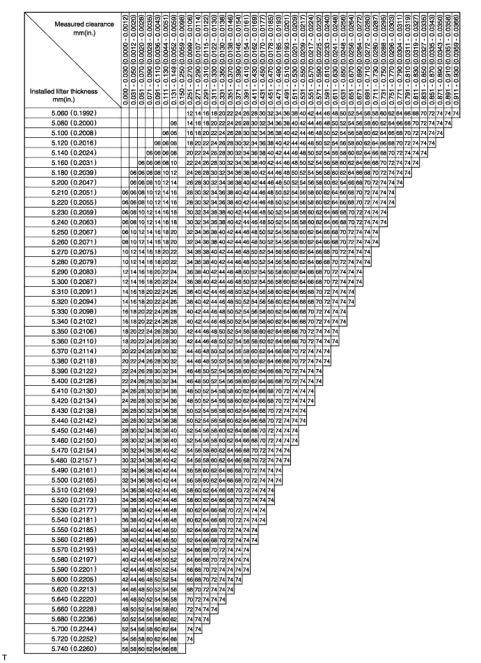
- Intake valve clearance (cold):
- 0.15 to 0.25 mm (0.006 to 0.010 in.)
- EXAMPLE:
- A 5.250 mm (0.2067 in.) lifter is installed, and the measured clearance is 0.400 mm (0.0158 in.). Replace the 5.250 mm (0.2067 in.) lifter with a new No. 46 lifter.
- New Shim Thickness:
Shim No. Thickness Shim No. Thickness Shim No. Thickness 06 5.060 (0.1992) 30 5.300 (0.2087) 54 5.540 (0.2181) 08 5.080 (0.2000) 32 5.320 (0.2094) 56 5.560 (0.2189) 10 5.100 (0.2008) 34 5.340 (0.2102) 58 5.580 (0.2197) 12 5.120 (0.2016) 36 5.360 (0.2110) 60 5.600 (0.2205) 14 5.140 (0.2024) 38 5.380 (0.2118) 62 5.620 (0.2213) 16 5.160 (0.2031) 40 5.400 (0.2126) 64 5.640 (0.2220) 18 5.180 (0.2039) 42 5.420 (0.2134) 66 5.660 (0.2228) 20 5.200 (0.2047) 44 5.440 (0.2142) 68 5.680 (0.2236) 22 5.220 (0.2055) 46 5.460 (0.2150) 70 5.700(0.2244) 24 5.240 (0.2063) 48 5.480 (0.2157) 72 5.720 (0.2252) 26 5.260 (0.2071) 50 5.500 (0.2165) 74 5.740 (0.2260) 28 5.280 (0.2079) 52 5.520 (0.2173)

- Exhaust valve clearance (Cold):
- 0.25 to 0.35 mm (0.010 to 0.014 in.)
- EXAMPLE:
- A 5.340 mm (0.2102 in.) lifter is installed, and the measured clearance is 0.440 mm (0.0173 in.). Replace the 5.340 mm (0.2102 in.) lifter with a new No. 48 lifter.
- New Shim Thickness:
Shim No. Thickness Shim No. Thickness Shim No. Thickness 06 5.060 (0.1992) 30 5.300 (0.2087) 54 5.540 (0.2181) 08 5.080 (0.2000) 32 5.320 (0.2094) 56 5.560 (0.2189) 10 5.100 (0.2008) 34 5.340 (0.2102) 58 5.580 (0.2197) 12 5.120 (0.2016) 36 5.360 (0.2110) 60 5.600 (0.2205) 14 5.140 (0.2024) 38 5.380 (0.2118) 62 5.620 (0.2213) 16 5.160 (0.2031) 40 5.400 (0.2126) 64 5.640 (0.2220) 18 5.180 (0.2039) 42 5.420 (0.2134) 66 5.660 (0.2228) 20 5.200 (0.2047) 44 5.440 (0.2142) 68 5.680 (0.2236) 22 5.220 (0.2055) 46 5.460 (0.2150) 70 5.700 (0.2244) 24 5.240 (0.2063) 48 5.480 (0.2157) 72 5.720 (0.2252) 26 5.260 (0.2071) 50 5.500 (0.2165) 74 5.740 (0.2260) 28 5.280 (0.2079) 52 5.520 (0.2173)
Install the selected valve lifter.
Apply a light coat of engine oil to the camshaft and camshaft journals.
Install the chain onto the camshaft timing gear with the paint mark and the timing mark aligned as shown in the illustration.
Text in Illustration *a Paint Mark *b Timing Mark
 |
Examine the front marks and the numbers on No. 2 camshaft bearing cap and check that the sequence is as shown in the illustration. Then uniformly tighten the bolts in several steps in the sequence shown in the illustration.
- Torque:
- 13 N*m{129 kgf*cm, 9.4 ft.*lbf}
- NOTICE:
- Tighten each bolt uniformly while keeping the camshaft level.
 |
Install No. 2 camshaft.
|
Hold the chain, and align the timing mark on the camshaft timing sprocket with the paint mark of the chain.
Text in Illustration *a Paint Mark *b Timing Mark *c Pin
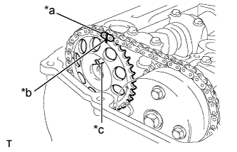 |
Align the alignment pin hole in the camshaft timing sprocket with the alignment pin of the camshaft, and install the sprocket onto the camshaft.
Provisionally install the flange bolt.
|
Examine the front marks and the numbers of camshaft No. 1 bearing cap and No. 2 camshaft bearing cap and check that the sequence is as shown in the illustration. Then uniformly tighten the bolts in several steps, in the sequence shown in the illustration.
Text in Illustration *a No. 1 Bearing Cap *b No. 2 Bearing Cap - Torque:
- No. 2 bearing cap:
- 13 N*m{129 kgf*cm, 9.4 ft.*lbf}
- No. 1 bearing cap:
- 23 N*m{235 kgf*cm, 17 ft.*lbf}
- NOTICE:
- Tighten each bolt uniformly while keeping the camshaft level.
 |
Using a union nut wrench 14 mm, hold the hexagonal lobe of camshaft No. 2 and install the flange bolt.
- Torque:
- 64 N*m{653 kgf*cm, 47 ft.*lbf}
- NOTICE:
- Use the formula to calculate special torque values for situations where a union nut wrench is combined with a torque wrench (YARIS_NCP93 RM00000482L007X.html).
 |
Remove the bar from the timing chain tensioner.
Turn the crankshaft damper and align its timing notch with the timing mark "0" of the oil pump.
Text in Illustration *a Timing Notch
 |
Check that all the pairs of timing marks are aligned.
Text in Illustration *a Paint Marks *b Timing Marks
|
Apply adhesive to the 2 or 3 threads of the screw plug.
- Adhesive:
- Toyota Genuine Adhesive 1324, Three Bond 1324 or Equivalent
Using an 8 mm hexagon wrench, install the screw plug.
- Torque:
- 15 N*m{153 kgf*cm, 11 ft.*lbf}
|
Install the engine mounting insulator sub-assembly RH (YARIS_NCP93 RM000001DDV00VX_01_0047.html). (for Hatchback)
Install the fan and generator V belt (YARIS_NCP93 RM000001DCG01DX_01_0001.html).
Adjust the fan and generator V belt (YARIS_NCP93 RM000001DCG01DX_01_0002.html).
Inspect the fan and generator V belt (YARIS_NCP93 RM000004VS7003X_01_0001.html).
| 10. INSTALL CYLINDER HEAD COVER SUB-ASSEMBLY |
 |
 | Seal Packing |
Apply seal packing to the cylinder head as shown in the illustration.
- Seal packing:
- Toyota Genuine Seal Packing Black, Three Bond 1207B or equivalent
- NOTICE:
- Remove any oil from the contact surfaces.
- Install the cylinder head cover within 3 minutes and tighten the bolts within 15 minutes after applying seal packing.
- Do not start the engine for at least 2 hours after the installation.
Install the cylinder head cover sub-assembly with the 9 bolts, 2 nuts and 2 seal washers.
 |
Tighten the 9 bolts and 2 nuts in the sequence shown in the illustration.
- Torque:
- 10 N*m{102 kgf*cm, 7 ft.*lbf}
Install the wire harness bracket with the bolt.
- Torque:
- 13 N*m{130 kgf*cm, 9 ft.*lbf}
Connect the connector and 4 wire harness clamps and connect the engine wire harness.
Connect the 4 fuel injector connectors.
| 11. CONNECT FUEL VAPOR FEED HOSE ASSEMBLY |
Connect fuel vapor feed hose assembly.
| 12. CONNECT VENTILATION HOSE |
Connect the ventilation hose.
| 13. INSTALL NO. 1 IGNITION COIL |
Install the 4 No. 1 ignition coils with the 4 bolts.
- Torque:
- 9.0 N*m{92 kgf*cm, 80 in.*lbf}
- NOTICE:
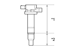
- If the body or cap of the ignition coil is dropped or subjected to a strong impact, replace the ignition coil with a new one.
Text in Illustration *1 Body *2 Cap - HINT:
- Perform "Inspection After Repairs" after replacing the ignition coil assembly (YARIS_NCP93 RM000004NJD006X.html).
Connect the 4 No. 1 ignition coil connectors.
| 14. CONNECT CABLE TO NEGATIVE BATTERY TERMINAL |
- Torque:
- 5.4 N*m{55 kgf*cm, 48 in.*lbf}
| 15. INSPECT FOR ENGINE OIL LEAK |
| 16. INSTALL NO. 2 CYLINDER HEAD COVER |
Install the No. 2 cylinder head cover with the 4 nuts.
- Torque:
- 7.0 N*m{71 kgf*cm, 62 in.*lbf}
| 17. INSTALL ENGINE UNDER COVER RH |
- Torque:
- 5.0 N*m{51 kgf*cm, 44 in.*lbf}