Dtc P2716 Pressure Control Solenoid D Electrical (Shift Solenoid Valve Slt)
DESCRIPTION
MONITOR DESCRIPTION
MONITOR STRATEGY
TYPICAL ENABLING CONDITIONS
TYPICAL MALFUNCTION THRESHOLDS
COMPONENT OPERATING RANGE
WIRING DIAGRAM
INSPECTION PROCEDURE
INSPECT TRANSMISSION WIRE (SHIFT SOLENOID VALVE SLT)
CHECK HARNESS AND CONNECTOR (TRANSMISSION WIRE - ECM)
INSPECT SHIFT SOLENOID VALVE SLT
DTC P2716 Pressure Control Solenoid "D" Electrical (Shift Solenoid Valve SLT) |
DESCRIPTION
Refer to P2714 (YARIS_NCP93 RM000000W830FNX_01.html).DTC No.
| DTC Detection Condition
| Trouble Area
|
P2716
| Open or short is detected in shift solenoid valve SLT circuit for 1 second or more while driving (1 trip detecting logic).
| - Wire harness or connector
- Transmission wire
- Shift solenoid valve SLT
- ECM
|
MONITOR DESCRIPTION
When an open or short in the linear solenoid valve (SLT) circuit is detected, the ECM interprets this as a fault. The ECM turns on the MIL and stores the DTC.
MONITOR STRATEGY
Related DTCs
| P2716: Shift solenoid valve SLT/Range check
|
Required sensors/Components
| Shift solenoid valve SLT
|
Frequency of operation
| Continuous
|
Duration
| 1.0 second
|
MIL operation
| Immediate
|
Sequence of operation
| None
|
TYPICAL ENABLING CONDITIONS
The monitor runs whenever the following DTCs are not present
| None
|
Solenoid current cut status
| Not cut
|
Battery voltage
| 11 V or more
|
CPU commanded duty ratio
| 19% or more
|
Ignition switch
| ON
|
Starter
| OFF
|
TYPICAL MALFUNCTION THRESHOLDS
Output signal monitor
| No signal
|
COMPONENT OPERATING RANGE
Output signal monitor
| Signal input
|
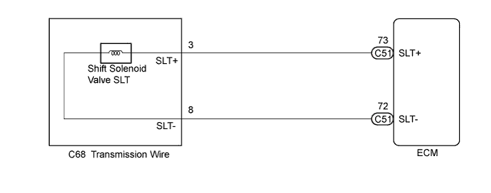
WIRING DIAGRAM
INSPECTION PROCEDURE
- NOTICE:
- Perform the universal trip to clear permanent DTCs (YARIS_NCP93 RM000000W770OEX.html).
| 1.INSPECT TRANSMISSION WIRE (SHIFT SOLENOID VALVE SLT) |
Disconnect the transmission wire connector from the transaxle.
Measure the resistance according to the value(s) in the table below.
- Standard Resistance:
Tester Connection
| Condition
| Specified Condition
|
3 (SLT+) - 8 (SLT-)
| 20°C (68°F)
| 5.0 to 5.6 Ω
|
3 (SLT+) - Body ground
| Always
| 10 kΩ or higher
|
8 (SLT-) - Body ground
| Always
| 10 kΩ or higher
|
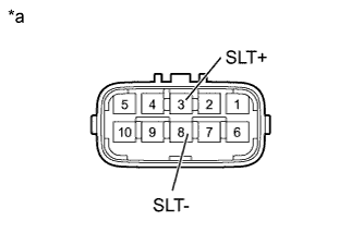
Text in Illustration*a
| Component without harness connected
(Transmission Wire)
|
| 2.CHECK HARNESS AND CONNECTOR (TRANSMISSION WIRE - ECM) |
Connect the transmission wire connector to the transaxle.
Disconnect the ECM connector.
Measure the resistance according to the value(s) in the table below.
- Standard Resistance:
Tester Connection
| Condition
| Specified Condition
|
C51-73 (SLT+) - C51-72 (SLT-)
| 20°C (68°F)
| 5.0 to 5.6 Ω
|
C51-73 (SLT+) - Body ground
| Always
| 10 kΩ or higher
|
C51-72 (SLT-) - Body ground
| Always
| 10 kΩ or higher
|
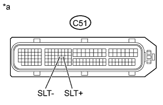
Text in Illustration*a
| Front view of wire harness connector
(to ECM)
|
| | REPAIR OR REPLACE HARNESS OR CONNECTOR |
|
|
| 3.INSPECT SHIFT SOLENOID VALVE SLT |
Remove shift solenoid valve SLT.
Measure the resistance according to the value(s) in the table below.
- Standard Resistance:
Tester Connection
| Condition
| Specified Condition
|
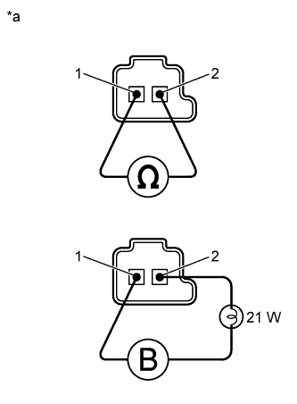
1 - 2
| 20°C (68°F)
| 5.0 to 5.6 Ω
|
Connect the positive (+) lead with a 21 W bulb to terminal 2 and the negative (-) lead to terminal 1 of the solenoid valve connector, then check the movement of the valve.
- OK:
- The solenoid makes operating sounds.
Text in Illustration*a
| Component without harness connected
(Shift Solenoid Valve SLT)
|