Dtc P0717 Turbine Speed Sensor Circuit No Signal
DESCRIPTION
MONITOR DESCRIPTION
MONITOR STRATEGY
TYPICAL ENABLING CONDITIONS
TYPICAL MALFUNCTION THRESHOLDS
COMPONENT OPERATING RANGE
WIRING DIAGRAM
INSPECTION PROCEDURE
INSPECT TRANSMISSION REVOLUTION SENSOR INSTALLATION
INSPECT TRANSMISSION REVOLUTION SENSOR
CHECK HARNESS AND CONNECTOR (TRANSMISSION REVOLUTION SENSOR - ECM)
DTC P0717 Turbine Speed Sensor Circuit No Signal |
DESCRIPTION
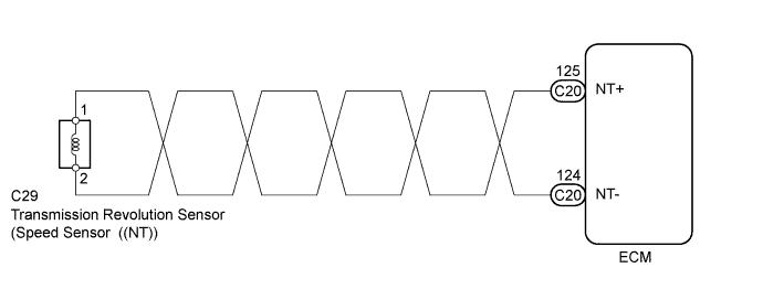
This sensor detects the rotation speed of the input turbine. By comparing the input turbine speed signal (NT) with the speed sensor signal (SPD), the ECM detects the shift timing of the gears and appropriately controls the engine torque and hydraulic pressure in response to various conditions, thus performing smooth gear shifting.DTC No.
| DTC Detection Condition
| Trouble Area
|
P0717
| All conditions below are detected for 5 seconds or more (1-trip detection logic).
(a) Gear change is not being performed.
(b) Gear position: 3rd or 4th.
(c) T/M input shaft rpm: Less than 300 rpm .
(d) T/M output shaft rpm: 1000 rpm or more.
(e) Park/neutral position switch (NSW, R and L) is OFF.
(f) Shift solenoid valves, park/neutral position switch and vehicle speed sensor are in normal operation.
| - Wire harness or connector
- Transmission revolution sensor (Speed sensor (NT))
- Automatic transaxle (clutch, brake or gear etc.)
- ECM
|
MONITOR DESCRIPTION
The ECM detects the revolving signal from the transmission revolution sensor (input speed). The ECM outputs a gearshift signal by comparing the transmission revolution sensor signal with the speed sensor signal (SPD). While the vehicle is operating in the 3rd or 4th gear position in the shift position of D, if the input shaft speed is less than 300 rpm*1 although the output shaft speed is 1000 rpm*2 or more, the ECM detects the malfunction, illuminates the MIL and stores the DTC.*1: Pulse is not output or is irregularly output.*2: The vehicle speed is 50 km/h (31 mph) or more.
MONITOR STRATEGY
Related DTCs
| P0717: Turbine speed sensor/Verify pulse input
|
Required sensors/Components
| Transmission revolution sensor (Speed sensor (NT))
|
Frequency of operation
| Continuous
|
Duration
| 5 seconds
|
MIL operation
| Immediate
|
Sequence of operation
| None
|
TYPICAL ENABLING CONDITIONS
Shift change
| After shift change is completed and before starting next shift change operation
|
ECM selected gear
| 3rd or 4th
|
Output shaft rpm
| 1000 rpm or more
|
Park/neutral position switch
| OFF
|
R switch
| OFF
|
L switch
| OFF
|
Transmission range switch fail (P0705)
| Not detected
|
Battery voltage
| 8 V or more
|
Ignition switch
| ON
|
Starter
| OFF
|
Engine
| Running
|
TYPICAL MALFUNCTION THRESHOLDS
Sensor signal rpm
| Less than 300 rpm
|
COMPONENT OPERATING RANGE
Transmission revolution sensor (Speed sensor (NT))
| Input turbine speed is equal to engine speed when lock-up ON
|
WIRING DIAGRAM
INSPECTION PROCEDURE
- NOTICE:
- Perform the universal trip to clear permanent DTCs (YARIS_NCP93 RM000000W770MGX.html).
| 1.INSPECT TRANSMISSION REVOLUTION SENSOR INSTALLATION |
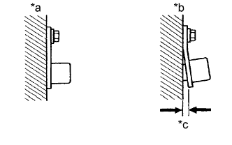
Check the transmission revolution sensor installation.
- OK:
- The installation bolt is tightened properly and there is no clearance between the sensor and transmission case.
Text in Illustration*a
| Correct
|
*b
| Incorrect
|
*c
| Clearance
|
| 2.INSPECT TRANSMISSION REVOLUTION SENSOR |
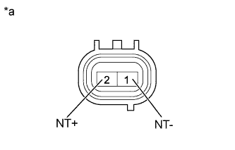
Disconnect the transmission revolution sensor connector from the transaxle.
Measure the resistance according to the value(s) in the table below.
- Standard Resistance:
Tester Connection
| Condition
| Specified Condition
|
1 - 2
| 20°C (68°F)
| 560 to 680 Ω
|
Text in Illustration*a
| Component without harness connected
(Transmission Revolution Sensor)
|
| 3.CHECK HARNESS AND CONNECTOR (TRANSMISSION REVOLUTION SENSOR - ECM) |
Connect the transmission revolution sensor connector.
Disconnect the ECM connector.
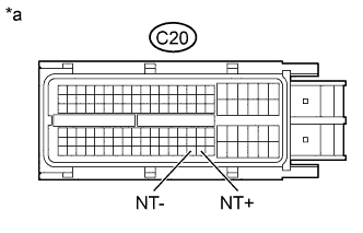
Measure the resistance according to the value(s) in the table below.
- Standard Resistance:
Tester Connection
| Condition
| Specified Condition
|
C20-125 (NT+) - C20-124 (NT-)
| 20°C (68°F)
| 560 to 680 Ω
|
C20-125 (NT+) - Body ground
| Always
| 10 kΩ or higher
|
C20-124 (NT-) - Body ground
| Always
| 10 kΩ or higher
|
Text in Illustration*a
| Front view of wire harness connector
(to ECM)
|
| | REPAIR OR REPLACE HARNESS OR CONNECTOR |
|
|