Anti-Lock Brake System (For Sedan) Ts And Cg Terminal Circuit
DESCRIPTION
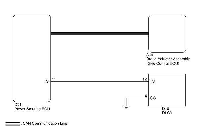
WIRING DIAGRAM
INSPECTION PROCEDURE
CHECK CAN COMMUNICATION SYSTEM
INSPECT DLC3
CHECK HARNESS AND CONNECTOR (TS of DLC3 - POWER STEERING ECU ASSEMBLY)
CHECK HARNESS AND CONNECTOR (CG of DLC3 - BODY GROUND)
INSPECT POWER STEERING ECU ASSEMBLY
ANTI-LOCK BRAKE SYSTEM (for Sedan) - TS and CG Terminal Circuit |
DESCRIPTION
In the Test Mode (signal check), a malfunction in the speed sensor that cannot be detected when the vehicle is stopped can be detected while driving.Transition to the sensor check mode can be performed by connecting terminals TS and CG of the DLC3 and turning the ignition switch from off to ON.
WIRING DIAGRAM
INSPECTION PROCEDURE
| 1.CHECK CAN COMMUNICATION SYSTEM |
Check if CAN communication system DTCs are output (YARIS_NCP93 RM000001D3E00OX.html).
ResultResult
| Proceed to
|
DTC is not output
| A
|
DTC is output
| B
|
Turn the ignition switch to ON.
Measure the voltage according to the value(s) in the table below.
- Standard Voltage:
Tester Connection
| Switch Condition
| Specified Condition
|
D15-12 (TS) - D15-4 (CG)
| Ignition switch ON
| 11 to 14 V
|
Text in Illustration*a
| Front view of DLC3
|
ResultResult
| Proceed to
|
NG
| A
|
OK
| B
|
| 3.CHECK HARNESS AND CONNECTOR (TS of DLC3 - POWER STEERING ECU ASSEMBLY) |
Turn the ignition switch off.
Disconnect the D31 power steering ECU connector.
Measure the resistance according to the value(s) in the table below.
- Standard Resistance:
Tester Connection
| Condition
| Specified Condition
|
D15-12 (TS) - D31-11 (TS)
| Always
| Below 1 Ω
|
D15-12 (TS) - Body ground
| Always
| 10 kΩ or higher
|
Reconnect the D31 power steering ECU connector.
| | REPAIR OR REPLACE HARNESS OR CONNECTOR |
|
|
| 4.CHECK HARNESS AND CONNECTOR (CG of DLC3 - BODY GROUND) |
Measure the resistance according to the value(s) in the table below.
- Standard Resistance:
Tester Connection
| Condition
| Specified Condition
|
D15-4 (CG) - Body ground
| Always
| Below 1 Ω
|
- HINT:
- If troubleshooting has been carried out according to Problem Symptoms Table, refer back to the table and proceed to the next step before replacing the part (YARIS_NCP93 RM000000XHN0AWX.html).
| | REPAIR OR REPLACE HARNESS OR CONNECTOR |
|
|
| 5.INSPECT POWER STEERING ECU ASSEMBLY |
- SST
- 09843-18040
Turn the ignition switch off.
Using SST, connect terminals TS and CG of the DLC3.
Turn the ignition switch to ON.
Check that the PS warning light is blinking.
Text in Illustration*a
| Front view of DLC3
|
ResultResult
| Proceed to
|
Check PS warning light is not blinking
| A
|
Check PS warning light is blinking
| B
|