Dtc C1421 Open Or Short In Master Cylinder Pressure Sensor
DESCRIPTION
WIRING DIAGRAM
INSPECTION PROCEDURE
REPLACE BRAKE ACTUATOR ASSEMBLY
DTC C1421 Open or Short in Master Cylinder Pressure Sensor |
DTC C1281 Master Cylinder Pressure Sensor Output Malfunction (Test Mode DTC) |
DTC C1423 Master Cylinder Pressure Sensor Zero Point Low Malfunction |
DTC C1424 Master Cylinder Pressure Sensor Output Malfunction |
DESCRIPTION
The master cylinder pressure sensor is connected to the skid control ECU in the brake actuator assembly.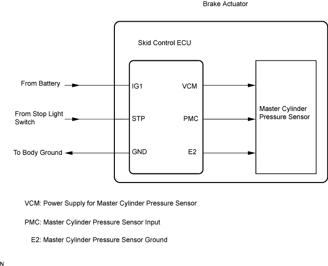
DTC Code
| DTC Detection Condition
| Trouble Area
|
C1421
| Either of the following is detected:
- With the IG1 terminal voltage between 9.5 and 17.4 V, the VCM terminal voltage is not between 4.4 and 5.6 V for 1.2 seconds or more.
- When the VCM terminal voltage is between 4.8 and 5.2 V, the PMC terminal voltage is not between 0.19 and 4.57 V for 1.2 seconds or more.
| Brake actuator assembly (Master cylinder pressure sensor)
|
C1281
| Detected only during Test Mode.
| Brake actuator assembly (Master cylinder pressure sensor)
|
C1423
| The PMC terminal voltage is less than 0.27 V for 5 seconds or more.
| Brake actuator assembly (Master cylinder pressure sensor)
|
C1424
| Any of the following is detected:
- Noise occurs in the PMC terminal 7 times or more within 5 seconds.
- When the vehicle speed drops from 40 km/h (25 mph) to 10 km/h (6 mph), the master cylinder pressure does not change by at least 0.048 MPa.
- At a vehicle speed of 7 km/h (4.3 mph) or more, the PMC terminal voltage is between 0.86 and 1.0 V and does not change by at least 0.048 MPa for 60 seconds or more.
- At a vehicle speed of 7 km/h (4.3 mph) or more, the PMC terminal voltage is 1.0 V or more and does not change by at least 0.048 MPa for 30 seconds or more.
- At a vehicle speed of 7 km/h (4.3 mph) or more with the stop switch ON, a state in which the pressure sensor input value is sufficiently greater than the estimated master pressure continues for 1 second of more and this state occurs 5 or more times each time the ignition switch is turned to ON, and this occurs 8 or more times consecutively.
| Brake actuator assembly (Master cylinder pressure sensor)
|
WIRING DIAGRAM
Refer to DTC C1425 (YARIS_NCP93 RM000000XIE0EZX_02.html).
INSPECTION PROCEDURE
- NOTICE:
- When replacing the brake actuator assembly, perform zero point calibration (YARIS_NCP93 RM000000XHR06QX.html).
- Inspect the fuses for circuits related to this system before performing the following inspection procedure.
| 1.REPLACE BRAKE ACTUATOR ASSEMBLY |
Replace the brake actuator assembly (master cylinder pressure sensor) (YARIS_NCP93 RM000001BXP02FX.html).