Dtc P0976 Shift Solenoid B Control Circuit Low (Shift Solenoid Valve S2)
DESCRIPTION
MONITOR DESCRIPTION
MONITOR STRATEGY
TYPICAL ENABLING CONDITIONS
TYPICAL MALFUNCTION THRESHOLDS
COMPONENT OPERATING RANGE
WIRING DIAGRAM
INSPECTION PROCEDURE
INSPECT TRANSMISSION WIRE (SHIFT SOLENOID VALVE S2)
CHECK HARNESS AND CONNECTOR (TRANSMISSION WIRE - ECM)
INSPECT SHIFT SOLENOID VALVE S2
DTC P0976 Shift Solenoid "B" Control Circuit Low (Shift Solenoid Valve S2) |
DTC P0977 Shift Solenoid "B" Control Circuit High (Shift Solenoid Valve S2) |
DESCRIPTION
Shifting from 1st to 4th is performed in combination with the ON and OFF operations of shift solenoid valves S1 and S2 which are controlled by the ECM. If an open or short circuit occurs in either of the shift solenoid valves, the ECM controls the remaining normal shift solenoid valve to allow the vehicle to be driven smoothly. (If an open or short circuit occurs, the ECM stops sending current to the affected circuit.) Fail-safe function (YARIS_NCP93 RM000000O8L0IEX.html).DTC No.
| DTC Detection Condition
| Trouble Area
|
P0976
| ECM detects short in solenoid valve S2 circuit 4 times when solenoid valve S2 is operated (1-trip detection logic).
| - Wire harness or connector
- Transmission wire
- Shift solenoid valve S2
- ECM
|
P0977
| ECM detects open in solenoid valve S2 circuit 4 times when solenoid valve S2 is not operated (1-trip detection logic).
| - Wire harness or connector
- Transmission wire
- Shift solenoid valve S2
- ECM
|
MONITOR DESCRIPTION
The ECM commands gear shifts by turning the shift solenoid valves ON/OFF. When there is an open or short circuit in the shift solenoid valve S2 circuit, the ECM detects the problem and the MIL comes on. Illuminating the MIL, the ECM performs the fail-safe and turns the other functioning shift solenoid valve ON/OFF. (If an open or short circuit occurs, the ECM stops sending current to the affected circuit.)
MONITOR STRATEGY
Related DTCs
| P0976: Shift solenoid valve S2/Range check (Low resistance)
P0977: Shift solenoid valve S2/Range check (High resistance)
|
Required sensors/Components
| Shift solenoid valve S2
|
Frequency of operation
| Continuous
|
Duration
| 0.128 seconds or more
|
MIL operation
| Immediate
|
Sequence of operation
| None
|
TYPICAL ENABLING CONDITIONS
P0976: Range check (Low resistance)The monitor runs whenever the following DTCs are not present.
| None
|
Solenoid
| ON
|
Time after solenoid OFF to ON
| 0.008 seconds or more
|
P0977: Range check (High resistance)The monitor runs whenever the following DTCs are not present.
| None
|
Solenoid
| OFF
|
Time after solenoid ON to OFF
| 0.008 seconds or more
|
TYPICAL MALFUNCTION THRESHOLDS
P0976: Range check (Low resistance)Shift solenoid valve S2 resistance
| 8 Ω or less
|
P0977: Range check (High resistance)Shift solenoid valve S2 resistance
| 100 kΩ or more
|
COMPONENT OPERATING RANGE
Shift solenoid valve S2 resistance
| 11 to 15 Ω at 20°C (68°F)
|
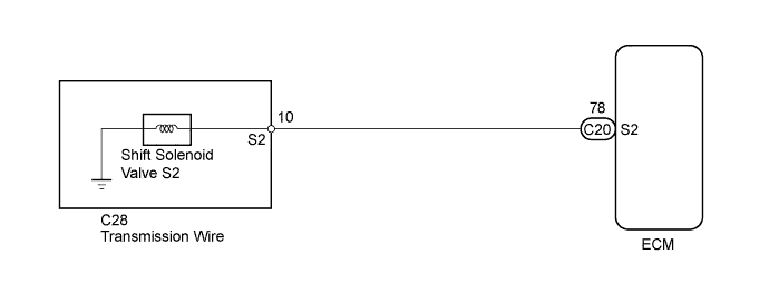
WIRING DIAGRAM
INSPECTION PROCEDURE
- NOTICE:
- Perform the universal trip to clear permanent DTCs (YARIS_NCP93 RM000000W770MGX.html).
- HINT:
- Shift solenoid valve S2 is turned on/off normally when the shift lever is in D:
Gearshift controlled by ECM
| 1st
| 2nd
| 3rd
| 4th
|
Shift solenoid valve S2
| ON
| OFF
| OFF
| ON
|
| 1.INSPECT TRANSMISSION WIRE (SHIFT SOLENOID VALVE S2) |
Disconnect the transmission wire connector from the transaxle.
Measure the resistance according to the value(s) in the table below.
- Standard Resistance:
Tester Connection
| Condition
| Specified Condition
|
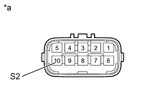
10 (S2) - Body ground
| 20°C (68°F)
| 11 to 15 Ω
|
Text in Illustration*a
| Component without harness connected
(Transmission Wire)
|
| 2.CHECK HARNESS AND CONNECTOR (TRANSMISSION WIRE - ECM) |
Connect the transmission connector to the transaxle.
Disconnect the ECM connector.
Measure the resistance according to the value(s) in the table below.
- Standard Resistance:
Tester Connection
| Condition
| Specified Condition
|
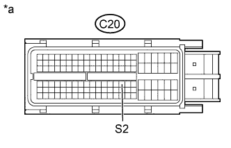
C20-78 (S2) - Body ground
| 20°C (68°F)
| 11 to 15 Ω
|
Text in Illustration*a
| Front view of wire harness connector
(to ECM)
|
| | REPAIR OR REPLACE HARNESS OR CONNECTOR |
|
|
| 3.INSPECT SHIFT SOLENOID VALVE S2 |
Remove shift solenoid valve S2.
Measure the resistance according to the value(s) in the table below.
- Standard Resistance:
Tester Connection
| Condition
| Specified Condition
|
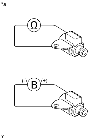
1 - Solenoid Body
| 20°C (68°F)
| 11 to 15 Ω
|
Connect the positive (+) lead to the terminal of the solenoid connector and the negative (-) lead to the solenoid body to check the solenoid valve operation.
- OK:
- The solenoid makes operating sounds.
Text in Illustration*a
| Component without harness connected
(Shift Solenoid Valve S2)
|