Dtc C1417 High Power Supply Voltage Malfunction
DESCRIPTION
WIRING DIAGRAM
INSPECTION PROCEDURE
INSPECT BATTERY
INSPECT SKID CONTROL ECU (IG1 TERMINAL)
RECONFIRM DTC
DTC C1417 High Power Supply Voltage Malfunction |
DESCRIPTION
If a malfunction is detected in the power supply circuit, the skid control ECU (housed in the actuator assembly) stores this DTC and the fail-safe function prohibits ABS operation.This DTC is stored when the IG1 terminal voltage deviates from the DTC detection condition due to a malfunction in the power supply or charging circuit such as the battery or generator circuit, etc.The DTC is cancelled when the IG1 terminal voltage returns to normal.DTC Code
| DTC Detection Condition
| Trouble Area
|
C1417
| The IG1 terminal voltage is 17.4 V or more for 0.8 seconds or more.
| - ECU-IG fuse
- Battery
- Charging system
- Power source circuit
- Internal power supply circuit of the skid control ECU
|
WIRING DIAGRAM
Refer to DTC C1241 (YARIS_NCP93 RM000000XW60BJX.html).
INSPECTION PROCEDURE
- NOTICE:
- When replacing the brake actuator assembly, perform zero point calibration (YARIS_NCP93 RM000000XHR06QX.html).
- Inspect the fuses for circuits related to this system before performing the following inspection procedure.
Check the battery voltage.
- Standard voltage:
- 11 to 14 V
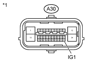
| 2.INSPECT SKID CONTROL ECU (IG1 TERMINAL) |
Make sure that there is no looseness at the locking part and the connecting part of the connectors.
Text in Illustration*1
| Front view of wire harness connector
(to Skid Control ECU)
|
Disconnect the A30 skid control ECU connector.
Turn the ignition switch to ON.
Measure the voltage according to the value(s) in the table below.
- Standard Voltage:
Tester Connection
| Switch Condition
| Specified Condition
|
A30-34 (IG1) - Body ground
| Ignition switch ON
| 11 to 14 V
|
- HINT:
- If troubleshooting has been carried out according to the Problem Symptoms Table, refer back to the table and proceed to the next step (YARIS_NCP93 RM000000XHN0AXX.html).
| | REPAIR OR REPLACE HARNESS OR CONNECTOR (IG1 CIRCUIT) |
|
|
Clear the DTCs (YARIS_NCP93 RM000000XHV0BQX.html).
Check if the same DTC is recorded (YARIS_NCP93 RM000000XHV0BQX.html).
ResultResult
| Proceed to
|
DTC (C1417) is not output
| A
|
DTC (C1417) is output
| B
|