Dtc C1241 Low Power Supply Voltage Malfunction
DESCRIPTION
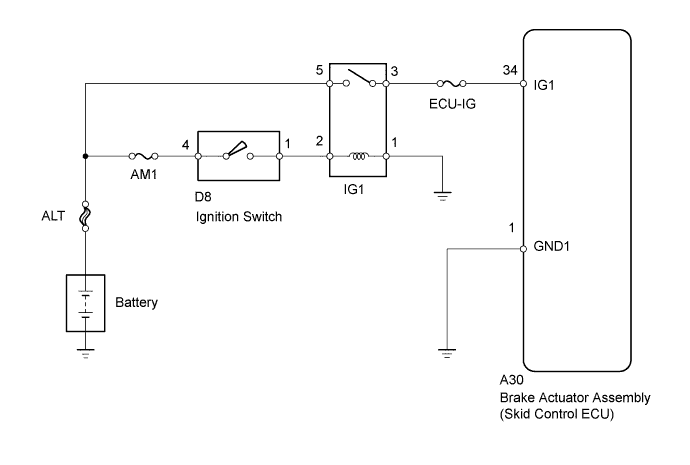
WIRING DIAGRAM
INSPECTION PROCEDURE
INSPECT BATTERY
INSPECT SKID CONTROL ECU (IG1 TERMINAL)
INSPECT SKID CONTROL ECU (GND TERMINAL)
RECONFIRM DTC
DTC C1241 Low Power Supply Voltage Malfunction |
DESCRIPTION
If a malfunction is detected in the power supply circuit, the skid control ECU (housed in the actuator assembly) stores this DTC and the fail-safe function prohibits ABS operation.This DTC is stored when the IG1 terminal voltage deviates from the DTC detection condition due to a malfunction in the power supply or charging circuit such as the battery or generator circuit, etc.The DTC is cancelled when the IG1 terminal voltage returns to normal.DTC Code
| DTC Detection Condition
| Trouble Area
|
C1241
| When any of the following is detected:
- At a vehicle speed of 3 km/h (2 mph) or more, the IG1 terminal voltage is less than 9.5 V for 10 seconds or more.
- When the solenoid relay remains ON and the IG1 terminal voltage is less than 9.5 V, the relay contact is open for 0.22 seconds or more.
- With the IG1 terminal voltage 9.5 V or less, the vehicle speed sensor power supply decreases for 60 seconds or more.
| - ECU-IG fuse
- Battery
- Charging system
- Power source circuit
- Internal power supply circuit of the skid control ECU
|
WIRING DIAGRAM
INSPECTION PROCEDURE
- NOTICE:
- When replacing the brake actuator assembly, perform zero point calibration (YARIS_NCP93 RM000000XHR06QX.html).
- Inspect the fuses for circuits related to this system before performing the following inspection procedure.
Check the battery voltage.
- Standard voltage:
- 11 to 14 V
| 2.INSPECT SKID CONTROL ECU (IG1 TERMINAL) |
Disconnect the A30 skid control ECU connector.
Turn the ignition switch to ON.
Measure the voltage according to the value(s) in the table below.
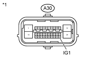
Text in Illustration*1
| Front view of wire harness connector
(to Skid Control ECU)
|
- Standard Voltage:
Tester Connection
| Switch Condition
| Specified Condition
|
A30-34 (IG1) - Body ground
| Ignition switch ON
| 11 to 14 V
|
| | REPAIR OR REPLACE HARNESS OR CONNECTOR (IG1 CIRCUIT) |
|
|
| 3.INSPECT SKID CONTROL ECU (GND TERMINAL) |
Turn the ignition switch off.
Measure the resistance according to the value(s) in the table below.
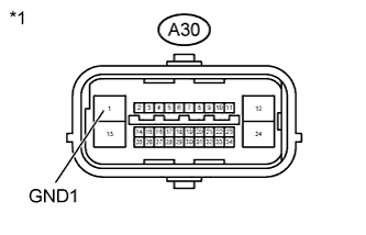
Text in Illustration*1
| Front view of wire harness connector
(to Skid Control ECU)
|
- Standard Resistance:
Tester Connection
| Condition
| Specified Condition
|
A30-1 (GND1) - Body ground
| Always
| Below 1 Ω
|
| | REPAIR OR REPLACE HARNESS OR CONNECTOR (GND CIRCUIT) |
|
|
Reconnect the skid control ECU connector.
Clear the DTC (YARIS_NCP93 RM000000XHV0BQX.html).
Start the engine.
Drive the vehicle at a speed of 20 km/h (12 mph) or more for 30 seconds or more.
Check if the same DTC is recorded (YARIS_NCP93 RM000000XHV0BQX.html).
ResultResult
| Proceed to
|
DTC is not output
| A
|
DTC is output
| B
|
- HINT:
- If troubleshooting has been carried out according to the Problem Symptoms Table, refer back to the table and proceed to the next step (YARIS_NCP93 RM000000XHN0AXX.html).