Tire Pressure Warning System (For Hatchback) Tire Pressure Warning Light Circuit
DESCRIPTION
WIRING DIAGRAM
INSPECTION PROCEDURE
CHECK FOR DTC (CAN COMMUNICATION SYSTEM)
PERFORM ACTIVE TEST USING TECHSTREAM (INDICAT. TIRE PRESSURE WARNING SYSTEM)
CHECK TIRE PRESSURE WARNING ECU AND RECEIVER (RDA TERMINAL)
CHECK HARNESS AND CONNECTOR (TIRE PRESSURE WARNING ECU AND RECEIVER - MAIN BODY ECU (MULTIPLEX NETWORK BODY ECU))
TIRE PRESSURE WARNING SYSTEM (for Hatchback) - Tire Pressure Warning Light Circuit |
DESCRIPTION
If the tire pressure warning ECU detects any problems, the tire pressure warning light blinks (stays on after blinking for 1 minute) and tire pressure monitoring is cancelled at the same time. At this time, the ECU stores a DTC in memory.Connecting terminals TC and CG of the DLC3 makes the tire pressure warning light blink to output DTCs.The tire pressure warning ECU and receiver sends the tire pressure warning light illumination request signal to the main body ECU (multiplex network body ECU) via a direct line. The main body ECU (multiplex network body ECU) then sends the signal to the combination meter assembly via CAN communication.
WIRING DIAGRAM
INSPECTION PROCEDURE
- NOTICE:
- When replacing the tire pressure warning ECU, read the transmitter IDs stored in the old ECU using the Techstream and write them down before removal.
- It is necessary to perform initialization (YARIS_NCP93 RM000000XMZ073X.html) after registration (YARIS_NCP93 RM000000XN107WX.html) of the transmitter IDs into the tire pressure warning ECU if the ECU has been replaced.
- When replacing the tire pressure warning ECU and receiver on vehicles equipped with the wireless door lock control system, be sure to perform Registration of Recognition Code to register the transmitter IDs after ECU replacement (YARIS_NCP93 RM0000023D302UX.html).
| 1.CHECK FOR DTC (CAN COMMUNICATION SYSTEM) |
Check if a CAN communication system DTC is output.
ResultResult
| Proceed to
|
DTCs is not output
| A
|
DTCs is output (for Hatchback except Separate Type Yaw Rate Sensor)
| B
|
DTCs is output (for Hatchback with Separate Type Yaw Rate Sensor)
| C
|
| 2.PERFORM ACTIVE TEST USING TECHSTREAM (INDICAT. TIRE PRESSURE WARNING SYSTEM) |
Turn the ignition switch off.
Connect the Techstream to the DLC3.
Turn the ignition switch to ON.
Turn the Techstream on.
Enter the following menus: Body Electrical / Combination Meter / Active Test.
Check the condition of the tire pressure warning light by using the Techstream.
Combination MeterTester Display
| Test Part
| Control Range
| Diagnostic Note
|
Indicat. Tire Pressure Warning System
| Tire pressure warning light
| Tire pressure warning light OFF or ON
| Confirm that the vehicle is stopped, engine idling
|
- OK:
- The tire pressure warning light turns on or off in accordance with the Techstream operation.
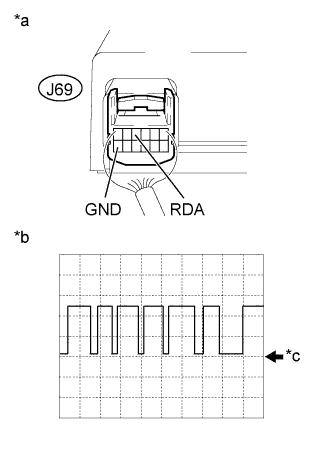
| 3.CHECK TIRE PRESSURE WARNING ECU AND RECEIVER (RDA TERMINAL) |
Disconnect the main body ECU (multiplex network body ECU) D143 connector.
Using an oscilloscope, check waveform.
Text in Illustration*a
| Component with harness connected
(Tire Pressure Warning ECU and Receiver)
|
*b
| Example
|
*c
| GND
|
Waveform:Item
| Contents
|
Terminal
| J69-4 (RDA) - J69-12 (GND)
|
Tool setting
| 5 V/DIV, 500 μs./DIV.
|
Vehicle condition
| Ignition switch ON
|
- OK:
- Waveform alternates between high and low, where high is a voltage that is between the IG power source voltage and a voltage 2.2 V lower than the IG power source voltage.
- HINT:
- The waveform shown in the illustration is an example. If the tester displays a waveform that alternates between high and low, where high is a voltage that is between the IG power source voltage and a voltage 2.2 V lower than the IG power source voltage, and where low is a voltage of between 0 and 1.2 V, the ECU can be judged normal.
| 4.CHECK HARNESS AND CONNECTOR (TIRE PRESSURE WARNING ECU AND RECEIVER - MAIN BODY ECU (MULTIPLEX NETWORK BODY ECU)) |
Disconnect the tire pressure warning ECU and receiver J69 connector.
Measure the resistance according to the value(s) in the table below.
- Standard Resistance:
Tester Connection
| Condition
| Specified Condition
|
J69-4 (RDA) - D143-26 (RDA)
| Always
| Below 1 Ω
|
D143-26 (RDA) - Body ground
| Always
| 10 kΩ or higher
|
| | REPAIR OR REPLACE HARNESS OR CONNECTOR |
|
|