INSTALL CLUTCH RELEASE WITH BEARING CYLINDER ASSEMBLY (for Manual Transaxle)
REMOVE CLUTCH RELEASE BLEEDER SUB-ASSEMBLY (for Manual Transaxle)
INSTALL CLUTCH RELEASE BLEEDER SUB-ASSEMBLY (for Manual Transaxle)
INSTALL CLUTCH RELEASE CYLINDER TO ACCUMULATOR TUBE (for Manual Transaxle)
INSTALL ORIFICE TO FLEXIBLE HOSE TUBE (for Manual Transaxle)
INSPECT AND ADJUST CLUTCH COVER ASSEMBLY (for Manual Transaxle)
Rear Crankshaft Oil Seal -- Installation |
- NOTICE:
- for Manual Transaxle:
- When the transaxle is removed, be sure to use a new clutch release with bearing cylinder and new installation bolts. Removal of the transaxle allows the compressed clutch release with bearing cylinder to return to its original position, and dust could damage the seal of the clutch release with bearing cylinder, possibly causing clutch fluid leaks.
| 1. INSTALL ENGINE REAR OIL SEAL |
Apply MP grease to the lip of a new oil seal.
- NOTICE:
- Do not allow foreign matter to contact the lip of the oil seal.
- Do not allow MP grease to contact the dust seal.
 |
Using SST and a hammer, tap in the oil seal until its surface is flush with the edges of the cylinder block and crankcase.
- SST
- 09223-15030
09950-70010(09951-07100)
- NOTICE:
- Wipe off any extra grease from the crankshaft.
- Do not tap in the oil seal at an angle.
| 2. INSTALL DRIVE PLATE AND RING GEAR SUB-ASSEMBLY (for CVT) |
Using SST, hold the crankshaft.
- SST
- 09330-00021
09213-58014(91551-80840)
 |
Install the front spacer, drive plate and rear spacer onto the crankshaft.
- HINT:
- The front driver plate spacer is reversible.
- As the rear drive plate spacer is not reversible, be sure to install it in the direction shown in the illustration.
 |
Clean the bolts and bolt holes.
 |
Apply adhesive to 2 or 3 threads at the end of the 8 bolts.
Text in Illustration *1 Adhesive - Adhesive:
- Toyota Genuine Adhesive 1324, Three Bond 1324 or equivalent
Uniformly install and tighten the 8 bolts in several steps in the sequence shown in the illustration.
- Torque:
- 88 N*m{897 kgf*cm, 65 ft.*lbf}
 |
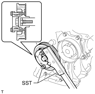
| 3. INSTALL FLYWHEEL SUB-ASSEMBLY (for Manual Transaxle) |
Using SST, hold the crankshaft.
- SST
- 09330-00021
09213-58014(91551-80840)
|
Clean the bolts and bolt holes.
|
Apply adhesive to 2 or 3 threads at the end of the 8 bolts.
Text in Illustration *1 Adhesive - Adhesive:
- Toyota Genuine Adhesive 1324, Three Bond 1324 or equivalent
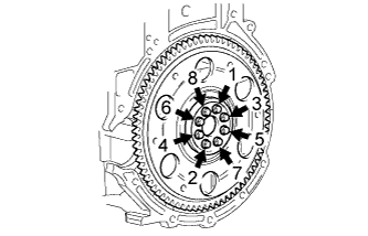
Uniformly install and tighten the 8 bolts in several steps in the sequence shown in the illustration.
- Torque:
- 49 N*m{500 kgf*cm, 36 ft.*lbf}
 |
Mark the top of the bolts with paint.
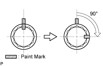 |
Retighten the 8 bolts an additional 90° in the same sequence.
Check that the paint marks are now at a 90° angle to the top.
| 4. INSTALL CLUTCH DISC ASSEMBLY (for Manual Transaxle) |
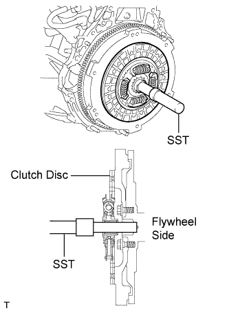 |
Insert SST into the clutch disc assembly, and then attach them both to the flywheel sub-assembly.
- SST
- 09301-00210
- NOTICE:
- Insert the clutch disc assembly in the correct direction.
| 5. INSTALL CLUTCH RELEASE WITH BEARING CYLINDER ASSEMBLY (for Manual Transaxle) |
Temporarily install the clutch release cylinder to bleeder tube to a new clutch release with bearing cylinder assembly.
 |
Clean and degrease all installation surfaces for the clutch release with bearing cylinder assembly.
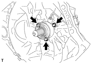
Install the clutch release with bearing cylinder assembly with 3 new bolts.
- Torque:
- 23 N*m{229 kgf*cm, 17 ft.*lbf}
- NOTICE:
- The clutch release with bearing cylinder and installation bolts cannot be reused and must be replaced with new ones.
- Clean and degrease all installation surfaces and make sure the clutch release with bearing cylinder fits securely with the transaxle during installation. The first bolt should be tightened by hand while holding the clutch release with bearing cylinder.
- Make sure that none of the clutch spline grease adheres to the clutch release with bearing cylinder.
- The clutch release with bearing cylinder cannot be disassembled.
 |
Install the clutch tube boot to the manual transaxle assembly.
 |
Temporarily install the clutch release cylinder to bleeder tube to the clutch release bleeder sub-assembly.
 |
Temporarily install the clutch release bleeder sub-assembly with the 2 bolts.
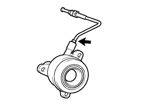
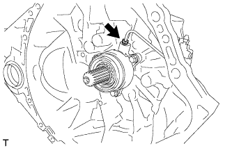
Using a union nut wrench, install the clutch release cylinder to bleeder tube to the clutch release with bearing cylinder assembly.
- Torque:
- 15 N*m{155 kgf*cm, 11 ft.*lbf}
- NOTICE:
- Use the formula to calculate special torque values for situations where a union nut wrench is combined with a torque wrench (RAV4_ACA30 RM0000018UO018X.html).
 |
Apply clutch spline grease to the input shaft spline.
- Grease:
- Toyota Genuine Clutch Spline Grease or equivalent
Text in Illustration *1 Clutch Spline Grease
 |
| 6. REMOVE CLUTCH RELEASE BLEEDER SUB-ASSEMBLY (for Manual Transaxle) |
Separate the clutch release cylinder to bleeder tube from the clutch release bleeder sub-assembly.
|
Remove the 2 bolts and clutch release bleeder sub-assembly.
| 7. INSPECT CLUTCH PIPE LINE (for Manual Transaxle) |
 |
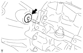
Using SST, apply a pressure of 100 kPa (1.0 kgf/cm2, 15 psi) to the clutch pipe location shown in the illustration and confirm that pressure is maintained for 15 seconds or more.
- SST
- 09992-00242
| 8. INSTALL CLUTCH RELEASE BLEEDER SUB-ASSEMBLY (for Manual Transaxle) |
Temporarily install the clutch release cylinder to bleeder tube to the clutch release bleeder sub-assembly.
|
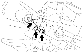
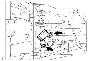
Install the clutch release bleeder sub-assembly with the 2 bolts.
- Torque:
- 17 N*m{170 kgf*cm, 12 ft.*lbf}
Using a union nut wrench, install the clutch release cylinder to bleeder tube.
- Torque:
- 15 N*m{155 kgf*cm, 11 ft.*lbf}
- NOTICE:
- Use the formula to calculate special torque values for situations where a union nut wrench is combined with a torque wrench (RAV4_ACA30 RM0000018UO018X.html).
| 9. INSTALL CLUTCH ORIFICE ASSEMBLY (for Manual Transaxle) |
 |
Install the clutch orifice assembly with the 2 bolts.
- Torque:
- 12 N*m{122 kgf*cm, 9 ft.*lbf}
| 10. INSTALL CLUTCH RELEASE CYLINDER TO ACCUMULATOR TUBE (for Manual Transaxle) |
 |
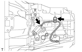
Using a union nut wrench, install the clutch release cylinder to accumulator tube.
- Torque:
- 15 N*m{155 kgf*cm, 11 ft.*lbf}
- NOTICE:
- Use the formula to calculate special torque values for situations where a union nut wrench is combined with a torque wrench (RAV4_ACA30 RM0000018UO018X.html).
| 11. INSTALL ORIFICE TO FLEXIBLE HOSE TUBE (for Manual Transaxle) |
 |
Temporarily tighten the orifice to flexible hose tube onto the clutch orifice assembly.
Install the orifice to flexible hose tube with the bolt.
- Torque:
- 12 N*m{122 kgf*cm, 9 ft.*lbf}
Using a union nut wrench, install the orifice to flexible hose tube.
- Torque:
- 15 N*m{155 kgf*cm, 11 ft.*lbf}
- NOTICE:
- Use the formula to calculate special torque values for situations where a union nut wrench is combined with a torque wrench (RAV4_ACA30 RM0000018UO018X.html).
| 12. INSTALL CLUTCH COVER ASSEMBLY (for Manual Transaxle) |
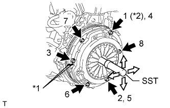 |
| *1 | Matchmark |
| *2 | Temporarily Install |
Align the matchmark on the clutch cover assembly with the one on the flywheel sub-assembly.
Following the order shown in the illustration, tighten the 6 bolts, starting with the bolt located near the knock pin at the top.
- SST
- 09301-00210
- Torque:
- 19 N*m{195 kgf*cm, 14 ft.*lbf}
- HINT:
- Following the order in the illustration, tighten the bolts evenly one at a time.
- Move SST up and down, right and left lightly after checking that the clutch disc assembly is in the center, and tighten the bolts.
| 13. INSPECT AND ADJUST CLUTCH COVER ASSEMBLY (for Manual Transaxle) |
Using a dial indicator with a roller instrument, check the diaphragm spring tip alignment.
- Maximum non-alignment:
- 0.5 mm (0.0196 in.)
- SST
- 09333-00013
 |
| 14. INSTALL MANUAL TRANSAXLE ASSEMBLY (for Manual Transaxle) |
for 2WD:
Install the manual transaxle assembly (RAV4_ACA30 RM000001B3U02LX.html).
for 4WD:
Install the manual transaxle assembly (RAV4_ACA30 RM000001B3U02WX.html).
| 15. INSTALL CONTINUOUSLY VARIABLE TRANSAXLE ASSEMBLY (for CVT) |
Install the continuously variable transaxle assembly (RAV4_ACA30 RM00000192D01ZX.html).
| 16. INSTALL ENGINE ASSEMBLY WITH TRANSAXLE |
Install the engine assembly with transaxle (RAV4_ACA30 RM000003PXM003X.html).