Door Lock. Toyota Rav4. Aca30, 33, 38 Gsa33 Zsa30, 35
DESCRIPTION
WIRING DIAGRAM
INSPECTION PROCEDURE
CHECK FOR DTC
CHECK MANUAL DOOR UNLOCK OPERATION
CHECK WIRELESS DOOR LOCK CONTROL OPERATION
READ VALUE USING INTELLIGENT TESTER (DOOR COURTESY LIGHT SWITCH)
READ VALUE USING INTELLIGENT TESTER (DOOR LOCK POSITION SWITCH)
PERFORM ACTIVE TEST USING INTELLIGENT TESTER (FRONT PASSENGER SIDE SELECT)
READ VALUE USING INTELLIGENT TESTER (TOUCH SENSOR)
CHECK ECU AGGREGATION BOX (OPERATION)
CHECK DOOR ELECTRICAL KEY OSCILLATOR (for Passenger Side)
CHECK WIRE HARNESS (DOOR ELECTRICAL KEY OSCILLATOR - ELECTRICAL KEY ANTENNA)
CHECK WIRE HARNESS (CERTIFICATION ECU - DOOR ELECTRICAL KEY OSCILLATOR)
ENTRY AND START SYSTEM - Front Passenger Side Door Entry Unlock Function does not Operate |
DESCRIPTION
- for LHD
When an ID code from the door electrical key oscillator RH matches the ID code from the key, the certification ECU outputs an SEL signal (Lo when output) to the door electrical key oscillator RH, activates the touch sensor located on the backside of the outside door handle, and enters unlock standby mode. When the touch sensor is touched, the door electrical key oscillator RH sends a SENS signal (Lo when output) to the certification ECU and the certification ECU sends an unlock signal to the front passenger side door lock.
- for RHD
When an ID code from the door electrical key oscillator LH matches the ID code from the key, the certification ECU outputs an SEL signal (Lo when output) to the door electrical key oscillator LH, activates the touch sensor located on the backside of the outside door handle, and enters unlock standby mode. When the touch sensor is touched, the door electrical key oscillator LH sends a SENS signal (Lo when output) to the certification ECU and the certification ECU sends an unlock signal to the front passenger side door lock.
WIRING DIAGRAM
INSPECTION PROCEDURE
Connect the intelligent tester to the DLC3.
Turn the ignition switch on (IG) and turn the tester ON.
By following the tester screen display, check whether any DTCs are output.
- OK:
- No DTC output.
| | Go to DIAGNOSTIC TROUBLE CODE CHART |
|
|
| 2.CHECK MANUAL DOOR UNLOCK OPERATION |
Check that all the doors unlock when the door control switch (for manual operation) is turned to UNLOCK.
- OK:
- All doors can be unlocked with door control switch.
| | Go to POWER DOOR LOCK CONTROL SYSTEM |
|
|
| 3.CHECK WIRELESS DOOR LOCK CONTROL OPERATION |
Check that the wireless door lock and unlock functions operates normally (RAV4_ACA30 RM000001VRW002X.html).
- OK:
- Wireless door lock and unlock functions operate normally.
| | Go to WIRELESS DOOR LOCK CONTROL SYSTEM (w/ ENTRY AND START SYSTEM) |
|
|
| 4.READ VALUE USING INTELLIGENT TESTER (DOOR COURTESY LIGHT SWITCH) |
Check the Data List for proper functioning of the door courtesy light switch (passenger side).
Main body ECU:Item
| Measurement Item / Range (Display)
| Normal Condition
| Diagnostic Note
|
P Door Courtesy SW
| Passenger side courtesy light switch signal / ON or OFF
| ON: Passenger side door is open
OFF: Passenger side door is closed
| -
|
- OK:
- On tester screen, item changes between ON and OFF according to above chart.
| 5.READ VALUE USING INTELLIGENT TESTER (DOOR LOCK POSITION SWITCH) |
Connect the intelligent tester to the DLC3.
Turn the ignition switch on (IG).
Turn the intelligent tester on.
Enter the following menus: Body / Main Body / Data List.
Read the Data List according to the display on the intelligent tester.
Main body ECU:Item
| Measurement Item / Range (Display)
| Normal Condition
| Diagnostic Note
|
P-Door Lock Pos SW
| Passenger side door lock position switch signal / ON or OFF
| ON: Passenger side door is unlocked
OFF: Passenger side door is locked
| -
|
- OK:
- On the intelligent tester screen, the display changes between ON and OFF as shown in the chart above.
| 6.PERFORM ACTIVE TEST USING INTELLIGENT TESTER (FRONT PASSENGER SIDE SELECT) |
Select the Active Test, use the intelligent tester to generate a control command, and then check that the door electrical key oscillator operates.
Certification ECU:Item
| Test Details
| Diagnostic Note
|
P-Seat Select
| Passenger side electrical key oscillator ON / OFF
| -
|
- OK:
- ON (P-Seat Select is ON) appears on screen.
| | REPLACE ECU AGGREGATION BOX (CERTIFICATION ECU) |
|
|
| 7.READ VALUE USING INTELLIGENT TESTER (TOUCH SENSOR) |
With "P-Seat Select" ON, check the Data List to confirm the operation of the touch sensor.
Certification ECU:Item
| Measurement Item / Range (Display)
| Normal Condition
| Diagnostic Note
|
P-Door Touch Sensor
| Front passenger side door touch sensor / ON or OFF
| ON: Sensor is touched
OFF: Sensor is not touched
| -
|
- OK:
- When passenger side door touch sensor is set to ON, ON (sensor is touched) appears on screen.
| 8.CHECK ECU AGGREGATION BOX (OPERATION) |
Temporarily replace the ECU aggregation box (certification ECU) with a new or normally functioning one.
Check that the entry unlock function operates normally (RAV4_ACA30 RM000001VGF003X.html).
- OK:
- Entry unlock function operates normally.
| | REPLACE INSTRUMENT PANEL JUNCTION BLOCK (MAIN BODY ECU) |
|
|
| OK |
|
|
|
| END (CERTIFICATION ECU IS DEFECTIVE) |
|
| 9.CHECK DOOR ELECTRICAL KEY OSCILLATOR (for Passenger Side) |
Measure the voltage of the oscillator.
- Standard voltage:
Tester Connection
| Condition
| Specified Condition
|
4 (SEL) - Body ground
| During Active Test
| Below 1 V
|
6 (SENS) - Body ground
| Touch sensor is touched during Active Test
| Below 1 V
|
Touch sensor is not touched during Active Test
| 10 to 14 V
|
| | REPLACE INSTRUMENT PANEL JUNCTION BLOCK (MAIN BODY ECU) |
|
|
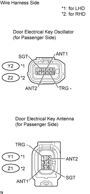
| 10.CHECK WIRE HARNESS (DOOR ELECTRICAL KEY OSCILLATOR - ELECTRICAL KEY ANTENNA) |
Disconnect the Y2*1 or Z2*2 oscillator connector.
Disconnect the Y1*1 or Z1*2 antenna connector.
Measure the resistance of the wire harness side connectors.
- HINT:
- *1: for LHD
- *2: for RHD
- Standard resistance:
- for LHD:
Tester Connection
| Specified Condition
|
Y2-2 (SGT) - Y1-6 (SGT)
| Below 1 Ω
|
Y2-3 (ANT1) - Y1-5 (ANT1)
|
Y2-8 (ANT2) - Y1-2 (ANT2)
|
Y2-9 (TRG-) - Y1-1 (TRG-)
|
Y2-2 (SGT) or Y1-6 (SGT) - Body ground
| 10 kΩ or higher
|
Y2-3 (ANT1) or Y1-5 (ANT1) - Body ground
|
Y2-8 (ANT2) or Y1-2 (ANT2) - Body ground
|
Y2-9 (TRG-) or Y1-1 (TRG-) - Body ground
|
- for RHD:
Tester Connection
| Specified Condition
|
Z2-2 (SGT) - Z1-6 (SGT)
| Below 1 Ω
|
Z2-3 (ANT1) - Z1-5 (ANT1)
|
Z2-8 (ANT2) - Z1-2 (ANT2)
|
Z2-9 (TRG-) - Z1-1 (TRG-)
|
Z2-2 (SGT) or Z1-6 (SGT) - Body ground
| 10 kΩ or higher
|
Z2-3 (ANT1) or Z1-5 (ANT1) - Body ground
|
Z2-8 (ANT2) or Z1-2 (ANT2) - Body ground
|
Z2-9 (TRG-) or Z1-1 (TRG-) - Body ground
|
| | REPAIR OR REPLACE HARNESS AND CONNECTOR |
|
|
| 11.CHECK WIRE HARNESS (CERTIFICATION ECU - DOOR ELECTRICAL KEY OSCILLATOR) |
Disconnect the E63 ECU connector.
Disconnect the Y2*1 or Z2*2 oscillator connector.
Measure the resistance of the wire harness side connectors.
- HINT:
- *1: for LHD
- *2: for RHD
- Standard resistance:
- for LHD:
Tester Connection
| Specified Condition
|
E63-6 (SEL2) - Y2-4 (SEL)
| Below 1 Ω
|
E63-23 (SEN2) - Y2-6 (SEN2)
|
E63-35 (CLG2) - Y2-10 (CLG)
|
E63-36 (DG2B) - Y2-5 (CLGB)
|
E63-6 (SEL2) or Y2-4 (SEL) - Body ground
| 10 kΩ or higher
|
E63-23 (SEN2) or Y2-6 (SEN2) - Body ground
|
E63-35 (CLG2) or Y2-10 (CLG) - Body ground
|
E63-36 (DG2B) or Y2-5 (CLGB) - Body ground
|
- for RHD:
Tester Connection
| Specified Condition
|
E63-6 (SEL2) - Z2-4 (SEL)
| Below 1 Ω
|
E63-23 (SEN2) - Z2-6 (SEN2)
|
E63-35 (CLG2) - Z2-10 (CLG)
|
E63-36 (DG2B) - Z2-5 (CLGB)
|
E63-6 (SEL2) or Z2-4 (SEL) - Body ground
| 10 kΩ or higher
|
E63-23 (SEN2) or Z2-6 (SEN2) - Body ground
|
E63-35 (CLG2) or Z2-10 (CLG) - Body ground
|
E63-36 (DG2B) or Z2-5 (CLGB) - Body ground
|
| | REPAIR OR REPLACE HARNESS AND CONNECTOR |
|
|
| OK |
|
|
|
| REPLACE DOOR ELECTRICAL KEY OSCILLATOR (for Passenger Side) |
|