Vehicle Stability Control System Ts And Cg Terminal Circuit
Brake. Toyota Rav4. Aca30, 33, 38 Gsa33 Zsa30, 35
DESCRIPTION
WIRING DIAGRAM
INSPECTION PROCEDURE
CHECK HARNESS AND CONNECTOR (DLC3 - SKID CONTROL ECU/BODY GROUND)
VEHICLE STABILITY CONTROL SYSTEM - TS and CG Terminal Circuit |
DESCRIPTION
If the vehicle is stationary during sensor check mode, speed sensor malfunctions cannot be detected. The vehicle must be driven for speed sensor malfunctions to be detected.- HINT:
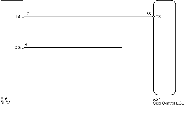
- Change to sensor check mode by connecting terminals 12 (TS) and 4 (CG) of the DLC3, and turning the ignition switch from off to ON.
WIRING DIAGRAM
INSPECTION PROCEDURE
- NOTICE:
- When replacing the brake actuator assembly, perform zero point calibration (RAV4_ACA30 RM000001K1O00SX.html).
| 1.CHECK HARNESS AND CONNECTOR (DLC3 - SKID CONTROL ECU/BODY GROUND) |
Disconnect the skid control ECU connector.
Measure the resistance according to the value(s) in the table below.
- Standard Resistance:
Tester Connection
| Condition
| Specified Condition
|
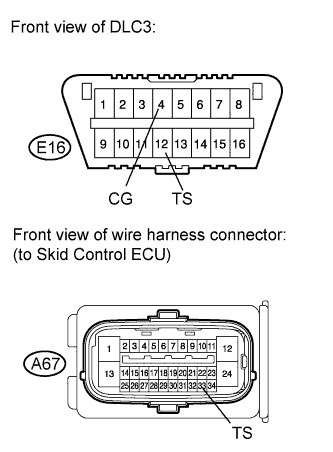
E16-4 (CG) - Body ground
| Always
| Below 1 Ω
|
E16-12 (TS) - A67-33 (TS)
| Always
| Below 1 Ω
|
A67-33 (TS) - Body ground
| Always
| 10 kΩ or higher
|
| | REPAIR OR REPLACE HARNESS OR CONNECTOR |
|
|