Dtc C0200/31 Right Front Wheel Speed Sensor Signal
Brake. Toyota Rav4. Aca30, 33, 38 Gsa33 Zsa30, 35
DESCRIPTION
WIRING DIAGRAM
INSPECTION PROCEDURE
CHECK HARNESS AND CONNECTOR (MOMENTARY INTERRUPTION)
READ VALUE USING INTELLIGENT TESTER (FRONT SPEED SENSOR)
PERFORM TEST MODE INSPECTION (SIGNAL CHECK)
RECONFIRM DTC
INSPECT FRONT SPEED SENSOR (INSTALLATION)
CHECK SPEED SENSOR (TIP)
CHECK WIRE HARNESS (SKID CONTROL ECU - FRONT SPEED SENSOR)
CHECK SKID CONTROL ECU (SENSOR INPUT VOLTAGE)
RECONFIRM DTC
REPLACE FRONT SPEED SENSOR
RECONFIRM DTC
DTC C0200/31 Right Front Wheel Speed Sensor Signal |
DTC C0205/32 Left Front Wheel Speed Sensor Signal |
DTC C1235/35 Foreign Object is Attached on Tip of Front Speed Sensor RH |
DTC C1236/36 Foreign Object is Attached on Tip of Front Speed Sensor LH |
DTC C1271/71 Low Output Signal of Front Speed Sensor RH (Test Mode DTC) |
DTC C1272/72 Low Output Signal of Front Speed Sensor LH (Test Mode DTC) |
DTC C1275/75 Abnormal Change in Output Signal of Front Speed Sensor RH (Test Mode DTC) |
DTC C1276/76 Abnormal Change in Output Signal of Front Speed Sensor LH (Test Mode DTC) |
DESCRIPTION
The speed sensors detect the wheel speeds and send appropriate signals to the skid control ECU.Speed sensor rotors have rows of alternating N and S magnetic poles, and their magnetic fields change as the rotors turn.The speed sensors detect those magnetic changes and send pulse signals to the skid control ECU. The ECU monitors the wheel speeds through these pulse signals to control the ABS control system.DTCs C1271/71, C1272/72, C1275/75 and C1276/76 can be deleted when the speed sensor sends a vehicle speed signal or the test mode ends. DTCs C1271/71, C1272/72, C1275/75/75 and C1276/76 are output only in the test mode.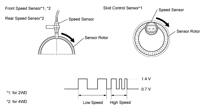
DTC No.
| DTC Detection Condition
| Trouble Area
|
C0200/31
C0205/32
| When one of following conditions is met:
- At vehicle speed of 10 km/h (6 mph) or more, open or short in sensor signal circuit continues for 1 second or more.
- Momentary interruption of sensor signal from abnormal wheel occurs 255 times or more.
- Open in speed sensor signal circuit continues for 0.5 seconds or more.
- With IG1 terminal voltage 9.5 V or more, sensor power supply voltage decreases for 0.5 seconds or more.
| - Front speed sensor
- Front speed sensor circuit
- Sensor installation
- Foreign matter on sensor rotor
- Brake actuator (Skid control ECU)
|
C1235/35
C1236/36
| When either of following is detected:
- At vehicle speed of 20 km/h (12 mph) or more, noise continues for 5 seconds or more in sensor signal from abnormal wheel.
- At vehicle speed of 10 km/h (6 mph) or more, noise input once per rotor rotation for 15 seconds or more.
| - Front speed sensor
- Front speed sensor circuit
- Sensor installation
- Brake actuator (Skid control ECU)
|
C1271/71
C1272/72
| Detected only during test mode.
| - Front speed sensor
- Front speed sensor circuit
- Sensor installation
- Foreign matter on sensor rotor
|
C1275/75
C1276/76
| Detected only during test mode.
| - Front speed sensor
- Front speed sensor circuit
- Sensor installation
|
- HINT:
- DTCs C0200/31 and C1235/35 relate to the front speed sensor RH.
- DTCs C0205/32 and C1236/36 relate to the front speed sensor LH.
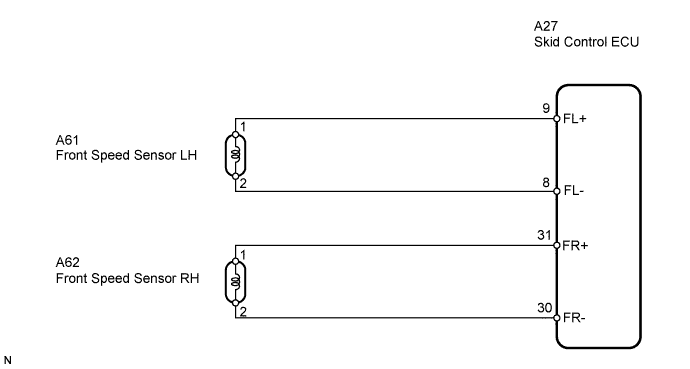
WIRING DIAGRAM
INSPECTION PROCEDURE
- NOTICE:
- Check the speed sensor signal in test mode after cleaning or replacement (RAV4_ACA30 RM000000ONN02FX.html).
| 1.CHECK HARNESS AND CONNECTOR (MOMENTARY INTERRUPTION) |
Using the Data List of the intelligent tester, check for any momentary interruption in the wire harness and connector corresponding to a DTC (RAV4_ACA30 RM000000XHS04PX.html).
Skid control ECUTester Display
| Measurement Item/Range
| Normal Condition
| Diagnostic Notes
|
FR Speed Open
| Front speed sensor RH open detection/ ERROR or NORMAL
| NORMAL
| -
|
FL Speed Open
| Front speed sensor LH open detection/ ERROR or NORMAL
| NORMAL
| -
|
- OK:
- NORMAL (There are no momentary interruptions).
- HINT:
- Perform the above inspection before removing the sensor and connector.
| | CHECK AND REPAIR HARNESS AND CONNECTOR (SPEED SENSOR CIRCUIT) |
|
|
| 2.READ VALUE USING INTELLIGENT TESTER (FRONT SPEED SENSOR) |
Check the Data List for proper functioning of the front speed sensor.
Skid control ECUTester Display
| Measurement Item/Range
| Normal Condition
| Diagnostic Notes
|
FR Wheel Speed
| Front speed sensor RH reading/ Min.: 0 km/h (0 mph), Max.: 326.4 km/h (202.8 mph)
| Actual wheel speed
| Similar to speed indicated on speedometer
|
FL Wheel Speed
| Front speed sensor LH reading/ Min.: 0 km/h (0 mph), Max.: 326.4 km/h (202.8 mph)
| Actual wheel speed
| Similar to speed indicated on speedometer
|
- OK:
- There is almost no difference between actual wheel speed and displayed speed value.
- HINT:
- There is a tolerance of +/-10% in the speedometer indication.
| 3.PERFORM TEST MODE INSPECTION (SIGNAL CHECK) |
Perform a test mode inspection and check for DTCs (RAV4_ACA30 RM000000ONN02FX.html).
- OK:
- No DTC output.
| | CHECK AND REPAIR HARNESS OR CONNECTOR (SPEED SENSOR CIRCUIT) |
|
|
Clear the DTC(s) (RAV4_ACA30 RM000000ONJ02UX.html).
Start the engine.
Drive the vehicle at a speed of 20 km/h (12 mph) or more for at least 60 seconds.
Check if the same DTC(s) is output (RAV4_ACA30 RM000000ONJ02UX.html).
ResultResult
| Proceed to
|
DTC is not output
| A
|
DTC is output
| B
|
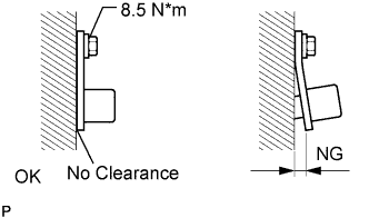
| 5.INSPECT FRONT SPEED SENSOR (INSTALLATION) |
Check that the speed sensor installation bolt is tightened properly.
- OK:
- The installation bolt is tightened properly, and there is no clearance between the sensor and front steering knuckle.
- Torque:
- 8.5 N*m (87 kgf*cm, 75 in.*lbf)
- HINT:
- If the installation portion of the sensor is dirty, clean it and reinstall the sensor.
| | TIGHTEN BOLT PROPERLY OR REPLACE FRONT SPEED SENSOR |
|
|
| 6.CHECK SPEED SENSOR (TIP) |
Remove the front speed sensor.
Check the sensor tip.
- OK:
- No scratches or foreign matter on the sensor tip.
| | CLEAN OR REPLACE FRONT SPEED SENSOR |
|
|
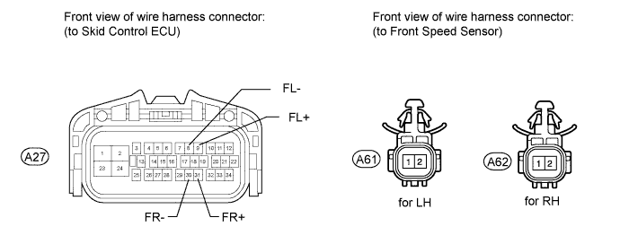
| 7.CHECK WIRE HARNESS (SKID CONTROL ECU - FRONT SPEED SENSOR) |
Disconnect the A27 ECU connector.
Disconnect the A61 and A62 sensor connectors.
Measure the resistance of the wire harness side connectors.
- Standard resistance:
- for LH:
Tester Connection
| Specified Condition
|
A27-9 (FL+) - A61-1
| Below 1 Ω
|
A27-8 (FL-) - A61-2
| Below 1 Ω
|
A27-9 (FL+) - Body ground
| 10 kΩ or higher
|
A27-8 (FL-) - Body ground
| 10 kΩ or higher
|
- for RH:
Tester Connection
| Specified Condition
|
A27-31 (FR+) - A62-1
| Below 1 Ω
|
A27-30 (FR-) - A62-2
| Below 1 Ω
|
A27-31 (FR+) - Body ground
| 10 kΩ or higher
|
A27-30 (FR-) - Body ground
| 10 kΩ or higher
|
| | REPAIR OR REPLACE HARNESS AND CONNECTOR |
|
|
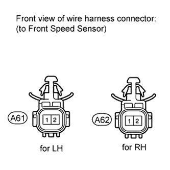
| 8.CHECK SKID CONTROL ECU (SENSOR INPUT VOLTAGE) |
Disconnect the A61 and A62 sensor connectors.
Measure the voltage of the wire harness side connectors.
- Standard voltage:
for LHTester Connection
| Switch Condition
| Specified Condition
|
A61-1 - Body ground
| Ignition switch ON
| 8 to 14 V
|
for RHTester Connection
| Switch Condition
| Specified Condition
|
A62-1 - Body ground
| Ignition switch ON
| 8 to 14 V
|
Clear the DTC(s) (RAV4_ACA30 RM000000ONJ02UX.html).
Start the engine.
Drive the vehicle at a speed of 20 km/h (12 mph) or more for at least 60 seconds.
Check if the same DTC(s) is output (RAV4_ACA30 RM000000ONJ02UX.html).
ResultResult
| Proceed to
|
DTC is output
| A
|
DTC is not output
| B
|
| 10.REPLACE FRONT SPEED SENSOR |
Replace the front speed sensor.
Clear the DTC(s) (RAV4_ACA30 RM000000ONJ02UX.html).
Start the engine.
Drive the vehicle at a speed of 20 km/h (12 mph) or more for at least 60 seconds.
Check if the same DTC(s) is output (RAV4_ACA30 RM000000ONJ02UX.html).
ResultResult
| Proceed to
|
DTC is output
| A
|
DTC is not output
| B
|