Vehicle Stability Control System Tc And Cg Terminal Circuit
Brake. Toyota Rav4. Aca30, 33, 38 Gsa33 Zsa30, 35
DESCRIPTION
WIRING DIAGRAM
INSPECTION PROCEDURE
CHECK DLC3 (TC VOLTAGE)
CHECK CAN COMMUNICATION SYSTEM
CHECK HARNESS AND CONNECTOR (DLC3 - ECM)
CHECK HARNESS AND CONNECTOR (DLC3 - BODY GROUND)
CHECK CAN COMMUNICATION SYSTEM
VEHICLE STABILITY CONTROL SYSTEM - TC and CG Terminal Circuit |
DESCRIPTION
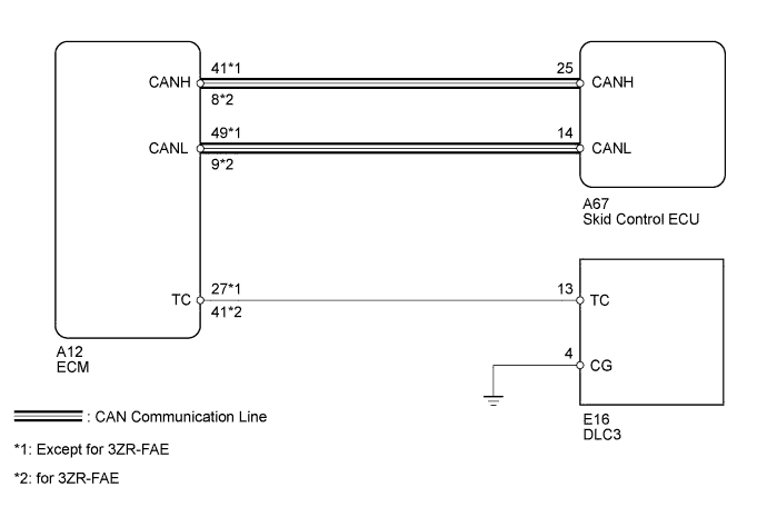
Connecting terminals 13 (TC) and 4 (CG) of the DLC3 causes the skid control ECU to output 2-digit DTCs by flashing the ABS warning light/slip indicator light.
WIRING DIAGRAM
INSPECTION PROCEDURE
- NOTICE:
- When replacing the brake actuator assembly, perform zero point calibration (RAV4_ACA30 RM000001K1O00SX.html).
| 1.CHECK DLC3 (TC VOLTAGE) |
Turn the ignition switch to ON.
Measure the voltage according to the value(s) in the table below.
- Standard Voltage:
Tester Connection
| Switch Condition
| Specified Condition
|
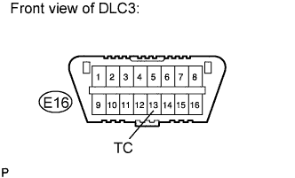
E16-13 (TC) - Body ground
| Ignition switch ON
| 11 to 14 V
|
| 2.CHECK CAN COMMUNICATION SYSTEM |
Check if a CAN communication system DTC is output (RAV4_ACA30 RM000001W16007X.html).
- Result:
Result
| Proceed to
|
DTC is not output.
| A
|
DTC is output.
| B
|
| 3.CHECK HARNESS AND CONNECTOR (DLC3 - ECM) |
Turn the ignition switch off.
Disconnect the ECM connector.
Measure the resistance according to the value(s) in the table below.
- Standard Resistance:
Except for 3ZR-FAE:Tester Connection
| Condition
| Specified Condition
|
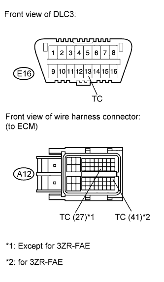
E16-13 (TC) - A12-27 (TC)
| Always
| Below 1 Ω
|
A12-27 (TC) - Body ground
| Always
| 10 kΩ or higher
|
for 3ZR-FAE:Tester Connection
| Condition
| Specified Condition
|
E16-13 (TC) - A12-27 (TC)
| Always
| Below 1 Ω
|
A12-41 (TC) - Body ground
| Always
| 10 kΩ or higher
|
| | REPAIR OR REPLACE HARNESS OR CONNECTOR |
|
|
| 4.CHECK HARNESS AND CONNECTOR (DLC3 - BODY GROUND) |
Measure the resistance according to the value(s) in the table below.
- Standard Resistance:
Tester Connection
| Condition
| Specified Condition
|
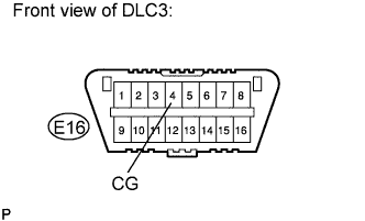
E16-4 (CG) - Body ground
| Always
| Below 1 Ω
|
| | REPAIR OR REPLACE HARNESS OR CONNECTOR |
|
|
| 5.CHECK CAN COMMUNICATION SYSTEM |
Check if a CAN communication system DTC is output (RAV4_ACA30 RM000001W16007X.html).
- Result:
Result
| Proceed to
|
DTC is not output.
| A
|
DTC is output.
| B
|