Anti-Lock Brake System Tc And Cg Terminal Circuit
Brake. Toyota Rav4. Aca30, 33, 38 Gsa33 Zsa30, 35
DESCRIPTION
WIRING DIAGRAM
INSPECTION PROCEDURE
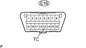
CHECK DLC3 (TC VOLTAGE)
CHECK CAN COMMUNICATION SYSTEM
CHECK WIRE HARNESS (DLC3 - ECM AND BODY GROUND)
CHECK WIRE HARNESS (DLC3 - BODY GROUND)
CHECK CAN COMMUNICATION SYSTEM
ANTI-LOCK BRAKE SYSTEM - TC and CG Terminal Circuit |
DESCRIPTION
Connecting terminals TC and CG of the DLC3 causes the skid control ECU to display 2-digit DTCs by flashing the ABS warning light.
WIRING DIAGRAM
INSPECTION PROCEDURE
| 1.CHECK DLC3 (TC VOLTAGE) |
Turn the ignition switch to ON.
Measure the voltage of the DLC3.
- Standard voltage:
Tester Connection
| Specified Condition
|
E16-13 (TC) - Body ground
| 11 to 14 V
|
| 2.CHECK CAN COMMUNICATION SYSTEM |
Check for DTC (RAV4_ACA30 RM000001RSW01ZX.html).
ResultResult
| Proceed to
|
DTC is not output
| A
|
DTC is output
| B
|
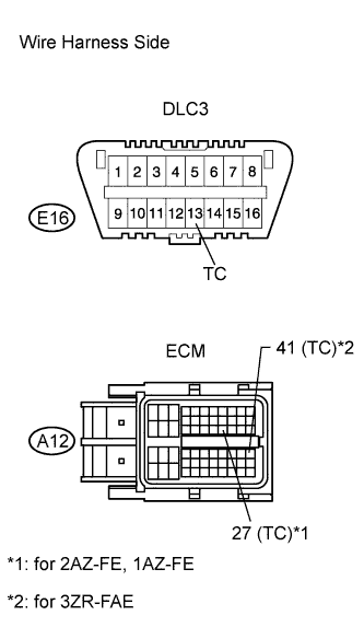
| 3.CHECK WIRE HARNESS (DLC3 - ECM AND BODY GROUND) |
Turn the ignition switch off.
Disconnect the A12 ECM connector.
Measure the resistance of the wire harness side connectors.
- Standard resistance:
for 2AZ-FE, 1AZ-FETester Connection
| Specified Condition
|
E16-13 (TC) - A12-27 (TC)
| Below 1 Ω
|
A12-27 (TC) - Body ground
| 10 kΩ or higher
|
for 3ZR-FAETester Connection
| Specified Condition
|
E16-13 (TC) - A12-41 (TC)
| Below 1 Ω
|
A12-41 (TC) - Body ground
| 10 kΩ or higher
|
| | REPAIR OR REPLACE HARNESS AND CONNECTOR |
|
|
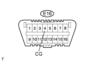
| 4.CHECK WIRE HARNESS (DLC3 - BODY GROUND) |
Measure the resistance of the DLC3.
- Standard resistance:
Tester Connection
| Specified Condition
|
E16-4 (CG) - Body ground
| Below 1 Ω
|
| | REPAIR OR REPLACE HARNESS AND CONNECTOR |
|
|
| 5.CHECK CAN COMMUNICATION SYSTEM |
Check if the CAN communication DTC is output (RAV4_ACA30 RM000001RSW01ZX.html).
ResultResult
| Proceed to
|
DTC is not output
| A
|
DTC is output
| B
|