INSTALL CLUTCH RELEASE WITH BEARING CYLINDER ASSEMBLY (for Manual Transaxle)
REMOVE CLUTCH RELEASE BLEEDER SUB-ASSEMBLY (for Manual Transaxle)
INSTALL CLUTCH RELEASE BLEEDER SUB-ASSEMBLY (for Manual Transaxle)
INSTALL CLUTCH RELEASE CYLINDER TO ACCUMULATOR TUBE (for Manual Transaxle)
INSTALL ORIFICE TO FLEXIBLE HOSE TUBE (for Manual Transaxle)
INSPECT AND ADJUST CLUTCH COVER ASSEMBLY (for Manual Transaxle)
INSTALL DRIVE PLATE AND TORQUE CONVERTER SETTING BOLT (for CVT)
INSTALL PROPELLER WITH CENTER BEARING SHAFT ASSEMBLY (for 4WD)
CONNECT TRANSMISSION CONTROL CABLE ASSEMBLY (for Manual Transaxle)
CONNECT COMPRESSOR WITH PULLEY ASSEMBLY (w/ Air Conditioning System)
Engine Assembly -- Installation |
- NOTICE:
- for Manual Transaxle:
- When the transaxle is removed, be sure to use a new clutch release with bearing cylinder and new installation bolts. Remove of the transaxle allows the compressed clutch release with bearing cylinder to return to its original position, and dust could damage the seal of the clutch release with bearing cylinder, possibly causing clutch fluid leaks.
| 1. INSTALL ENGINE MOUNTING INSULATOR LH |
- HINT:
 |
- Perform this procedure only when replacement of the engine mounting insulator is necessary.
Temporarily install the engine mounting insulator with the 4 bolts.
Tighten the 4 bolts in the sequence shown in the illustration.
- Torque:
- 95 N*m{969 kgf*cm, 70 ft.*lbf}
Install the wire harness clamp bracket with the bolt.
- Torque:
- 7.7 N*m{79 kgf*cm, 68 in.*lbf}
| 2. INSTALL ENGINE MOUNTING INSULATOR SUB-ASSEMBLY RH |
- HINT:
 |
- Perform this procedure only when replacement of the engine mounting insulator is necessary.
Temporarily install the engine mounting insulator with the 3 bolts.
Tighten the 3 bolts in the sequence shown in the illustration.
- Torque:
- 95 N*m{969 kgf*cm, 70 ft.*lbf}
Install the radiator reservoir bracket with the bolt.
- Torque:
- 5.0 N*m{51 kgf*cm, 44 in.*lbf}
| 3. INSTALL REAR ENGINE MOUNTING INSULATOR |
- HINT:
 |
- Perform this procedure only when replacement of the engine mounting insulator is necessary.
Temporarily install the engine mounting insulator with the 2 bolts and 2 nuts.
Tighten the 2 bolts and 2 nuts in the sequence shown in the illustration.
- Torque:
- 95 N*m{969 kgf*cm, 70 ft.*lbf}
| 4. INSTALL DRIVE SHAFT BEARING BRACKET |
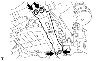
Install the drive shaft bearing bracket with the 3 bolts.
- Torque:
- 64 N*m{650 kgf*cm, 47 ft.*lbf}
 |
| 5. INSTALL ENGINE HANGER |
Disconnect the air fuel ratio sensor connector and remove the bolt and air fuel ratio sensor bracket.
 |
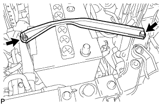
Install the No. 1 and No. 2 engine hangers with 2 bolts as shown in the illustration.
- Torque:
- 43 N*m{438 kgf*cm, 32 ft.*lbf}
Text in Illustration *1 No. 1 Engine Hanger *2 No. 2 Engine Hanger - HINT:
No. 1 Engine Hanger 12281-37021 No. 2 Engine Hanger 12282-37011 Bolt 91552-81050
 |
Attach an engine sling device and hang the engine with a chain block.
| 6. REMOVE ENGINE STAND |
Attach an engine sling device and hang the engine with a chain block.
Lift the engine and remove it from the engine stand.
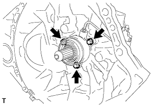
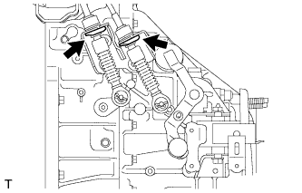
| 7. INSTALL CLUTCH RELEASE WITH BEARING CYLINDER ASSEMBLY (for Manual Transaxle) |
Temporarily install the clutch release cylinder to bleeder tube to a new clutch release with bearing cylinder assembly.
 |
Clean and degrease all installation surfaces for the clutch release with bearing cylinder assembly.
Install the clutch release with bearing cylinder assembly with 3 new bolts.
- Torque:
- 23 N*m{229 kgf*cm, 17 ft.*lbf}
- NOTICE:
- The clutch release with bearing cylinder and installation bolts cannot be reused and must be replaced with new ones.
- Clean and degrease all installation surfaces and make sure the clutch release with bearing cylinder fits securely with the transaxle during installation. The first bolt should be tightened by hand while holding the clutch release with bearing cylinder.
- Make sure that none of the clutch spline grease adheres to the clutch release with bearing cylinder.
- The clutch release with bearing cylinder cannot be disassembled.
 |
Install the clutch tube boot to the manual transaxle assembly.
 |
Temporarily install the clutch release cylinder to bleeder tube to the clutch release bleeder sub-assembly.
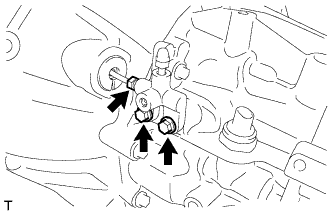 |
Temporarily install the clutch release bleeder sub-assembly with the 2 bolts.
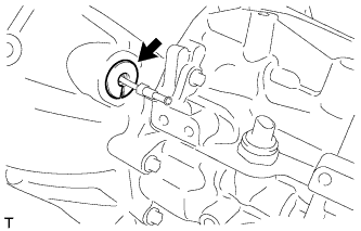
Using a union nut wrench, install the clutch release cylinder to bleeder tube to the clutch release with bearing cylinder assembly.
- Torque:
- 15 N*m{155 kgf*cm, 11 ft.*lbf}
- NOTICE:
- Use the formula to calculate special torque values for situations where a union nut wrench is combined with a torque wrench (RAV4_ACA30 RM0000018UO018X.html).
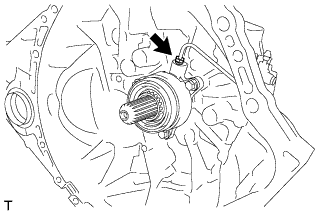 |
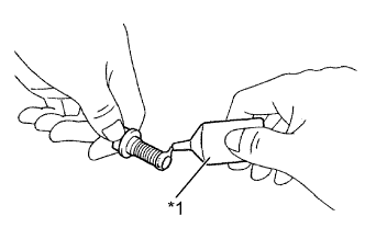
Apply clutch spline grease to the input shaft spline.
- Grease:
- Toyota Genuine Clutch Spline Grease or equivalent
Text in Illustration *1 Clutch Spline Grease
 |
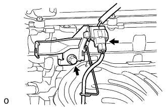
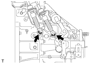
| 8. REMOVE CLUTCH RELEASE BLEEDER SUB-ASSEMBLY (for Manual Transaxle) |
Separate the clutch release cylinder to bleeder tube from the clutch release bleeder sub-assembly.
|
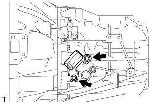
Remove the 2 bolts and clutch release bleeder sub-assembly.
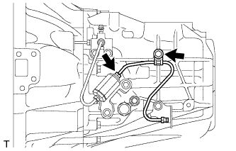
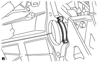
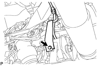
| 9. INSPECT CLUTCH PIPE LINE (for Manual Transaxle) |
 |
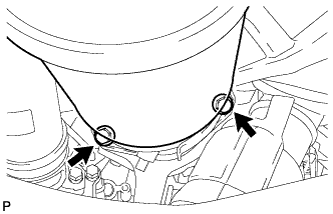
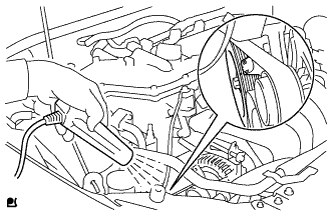
Using SST, apply a pressure of 100 kPa (1.0 kgf/cm2, 15 psi) to the clutch pipe location shown in the illustration and confirm that pressure is maintained for 15 seconds or more.
- SST
- 09992-00242
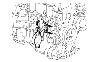
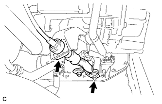
| 10. INSTALL CLUTCH RELEASE BLEEDER SUB-ASSEMBLY (for Manual Transaxle) |
Temporarily install the clutch release cylinder to bleeder tube to the clutch release bleeder sub-assembly.
|
Install the clutch release bleeder sub-assembly with the 2 bolts.
- Torque:
- 17 N*m{170 kgf*cm, 12 ft.*lbf}
Using a union nut wrench, install the clutch release cylinder to bleeder tube.
- Torque:
- 15 N*m{155 kgf*cm, 11 ft.*lbf}
- NOTICE:
- Use the formula to calculate special torque values for situations where a union nut wrench is combined with a torque wrench (RAV4_ACA30 RM0000018UO018X.html).
| 11. INSTALL CLUTCH ORIFICE ASSEMBLY (for Manual Transaxle) |
 |
Install the clutch orifice assembly with the 2 bolts.
- Torque:
- 12 N*m{122 kgf*cm, 9 ft.*lbf}
| 12. INSTALL CLUTCH RELEASE CYLINDER TO ACCUMULATOR TUBE (for Manual Transaxle) |
 |
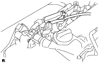
Using a union nut wrench, install the clutch release cylinder to accumulator tube.
- Torque:
- 15 N*m{155 kgf*cm, 11 ft.*lbf}
- NOTICE:
- Use the formula to calculate special torque values for situations where a union nut wrench is combined with a torque wrench (RAV4_ACA30 RM0000018UO018X.html).
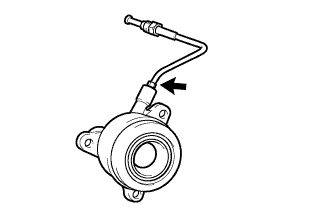
| 13. INSTALL ORIFICE TO FLEXIBLE HOSE TUBE (for Manual Transaxle) |
 |
Temporarily tighten the orifice to flexible hose tube onto the clutch orifice assembly.
Install the orifice to flexible hose tube with the bolt.
- Torque:
- 12 N*m{122 kgf*cm, 9 ft.*lbf}
Using a union nut wrench, install the orifice to flexible hose tube.
- Torque:
- 15 N*m{155 kgf*cm, 11 ft.*lbf}
- NOTICE:
- Use the formula to calculate special torque values for situations where a union nut wrench is combined with a torque wrench (RAV4_ACA30 RM0000018UO018X.html).
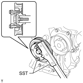
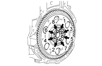
| 14. INSTALL FLYWHEEL SUB-ASSEMBLY (for Manual Transaxle) |
Using SST, hold the crankshaft.
- SST
- 09330-00021
09213-58014(91551-80840)
 |
Clean the bolts and bolt holes.
 |
Apply adhesive to 2 or 3 threads at the end of the 8 bolts.
Text in Illustration *1 Adhesive - Adhesive:
- Toyota Genuine Adhesive 1324, Three Bond 1324 or equivalent
Uniformly install and tighten the 8 bolts in several steps in the sequence shown in the illustration.
- Torque:
- 49 N*m{500 kgf*cm, 36 ft.*lbf}
 |
Mark the top of the bolts with paint.
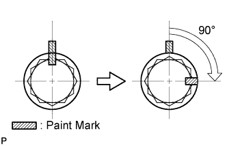 |
Retighten the 8 bolts an additional 90° in the same sequence.
Check that the paint marks are now at a 90° angle to the top.
| 15. INSTALL CLUTCH DISC ASSEMBLY (for Manual Transaxle) |
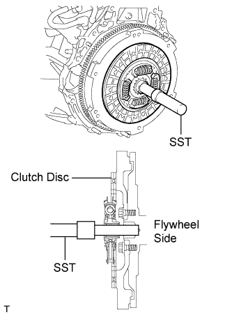 |
Insert SST into the clutch disc assembly, and then attach them both to the flywheel sub-assembly.
- SST
- 09301-00210
- NOTICE:
- Insert the clutch disc assembly in the correct direction.
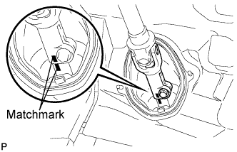
| 16. INSTALL CLUTCH COVER ASSEMBLY (for Manual Transaxle) |
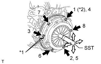 |
| *1 | Matchmark |
| *2 | Temporarily Install |
Align the matchmark on the clutch cover assembly with the one on the flywheel sub-assembly.
Following the order shown in the illustration, tighten the 6 bolts, starting with the bolt located near the knock pin at the top.
- SST
- 09301-00210
- Torque:
- 19 N*m{195 kgf*cm, 14 ft.*lbf}
- HINT:
- Following the order in the illustration, tighten the bolts evenly one at a time.
- Move SST up and down, right and left lightly after checking that the clutch disc assembly is in the center, and tighten the bolts.
| 17. INSPECT AND ADJUST CLUTCH COVER ASSEMBLY (for Manual Transaxle) |
Using a dial indicator with a roller instrument, check the diaphragm spring tip alignment.
- Maximum non-alignment:
- 0.5 mm (0.0196 in.)
- SST
- 09333-00013
 |
| 18. INSTALL DRIVE PLATE AND RING GEAR SUB-ASSEMBLY (for CVT) |
Using SST, hold the crankshaft.
- SST
- 09330-00021
09213-58014(91551-80840)
|
Install the front spacer, drive plate and rear spacer onto the crankshaft.
- HINT:
- The front driver plate spacer is reversible.
- As the rear drive plate spacer is not reversible, be sure to install it in the direction shown in the illustration.
 |
Clean the bolts and bolt holes.
|
Apply adhesive to 2 or 3 threads at the end of the 8 bolts.
Text in Illustration *1 Adhesive - Adhesive:
- Toyota Genuine Adhesive 1324, Three Bond 1324 or equivalent
Uniformly install and tighten the 8 bolts in several steps in the sequence shown in the illustration.
- Torque:
- 88 N*m{897 kgf*cm, 65 ft.*lbf}
 |
| 19. INSTALL MANUAL TRANSAXLE ASSEMBLY (for Manual Transaxle) |
for 2WD:
Install the manual transaxle assembly (RAV4_ACA30 RM000001B3U02LX.html).
for 4WD:
Install the manual transaxle assembly (RAV4_ACA30 RM000001B3U02WX.html).
| 20. INSTALL CONTINUOUSLY VARIABLE TRANSAXLE ASSEMBLY (for CVT) |
Install the continuously variable transaxle assembly (RAV4_ACA30 RM00000192D01ZX.html).
| 21. INSTALL FLYWHEEL HOUSING SIDE COVER |
Install the flywheel housing side cover to the cylinder block.
 |
| 22. INSTALL STARTER ASSEMBLY |
Install the starter with the 2 bolts.
- Torque:
- 37 N*m{380 kgf*cm, 27 ft.*lbf}
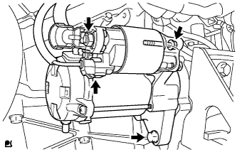 |
Connect the starter connector.
Connect starter wire with the nut.
- Torque:
- 9.8 N*m{100 kgf*cm, 87 in.*lbf}
Connect the terminal cap.
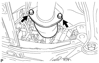
| 23. INSTALL FRONT SUSPENSION CROSSMEMBER SUB-ASSEMBLY |
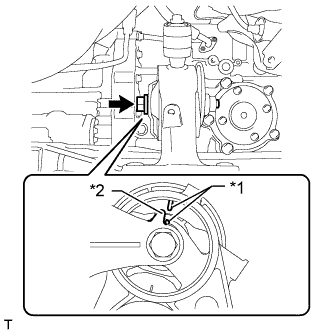
Install the suspension crossmember to the engine with the bolt.
Text in Illustration *1 Alignment Mark *2 Protrusion - Torque:
- 95 N*m{969 kgf*cm, 70 ft.*lbf}
- HINT:
- When installing the suspension crossmember, align the protrusion of the engine mounting bracket with the alignment mark of the engine mounting insulator.
 |
| 24. INSTALL NO. 1 STEERING COLUMN HOLE COVER SUB-ASSEMBLY |
Install the steering column hole cover to the steering gear with a new clamp.
| 25. INSTALL STEERING GEAR HEAT INSULATOR (for RHD) |
Install the heat insulator and bolt to the steering gear.
- Torque:
- 8.0 N*m{82 kgf*cm, 71 in.*lbf}
| 26. INSTALL ENGINE WIRE |
Install the engine wire to the engine.
| 27. INSTALL ENGINE AND TRANSAXLE |
Place the engine on an engine lifter.
- HINT:
- Place the engine on wooden blocks or equivalent so that the engine is level.
Remove the 2 bolts and engine hangers.
Text in Illustration *1 No. 1 Engine Hanger *2 No. 2 Engine Hanger
|
Operate the engine lifter and install the engine to the vehicle.
- NOTICE:
- Make sure that the engine is clear of all wiring and hoses.
Temporarily install the front suspension crossmember with the 2 bolts.
 |
Temporarily install the member brace rear RH and LH with the 6 bolts.
Install the engine mounting insulator LH with the bolt and nut.
- Torque:
- 56 N*m{571 kgf*cm, 41 ft.*lbf}
- NOTICE:
- While holding the bolt in place, tighten the nut.
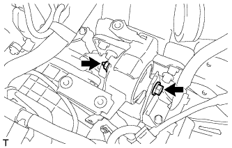 |
Install the engine mounting insulator RH with the bolt and 2 nuts.
- Torque:
- for bolt and nut A:
- 95 N*m{969 kgf*cm, 70 ft.*lbf}
- for nut B:
- 52 N*m{530 kgf*cm, 38 ft.*lbf}
 |
Tighten the front suspension member bolts.
- Torque:
- for bolt A:
- 137 N*m{1397 kgf*cm, 101 ft.*lbf}
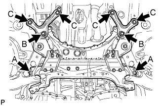 |
Tighten the member brace rear bolts.
- Torque:
- for bolt B:
- 137 N*m{1397 kgf*cm, 101 ft.*lbf}
- for bolt C:
- 93 N*m{948 kgf*cm, 69 ft.*lbf}
Install the air fuel ratio sensor bracket with the bolt. Then connect the air fuel ratio sensor connector.
- Torque:
- 60 N*m{612 kgf*cm, 44 ft.*lbf}
|
| 28. TEMPORARILY INSTALL FRONT ENGINE MOUNTING INSULATOR |
Temporarily install the engine mounting insulator with the bolt and nut.
 |
| 29. INSTALL FRONT CROSSMEMBER SUB-ASSEMBLY |
Install the crossmember with the 6 bolts.
- Torque:
- for bolt A:
- 96 N*m{979 kgf*cm, 71 ft.*lbf}
- for bolt B:
- 95 N*m{969 kgf*cm, 70 ft.*lbf}
 |
Tighten the bolt and nut holding the engine mounting insulator.
- Torque:
- 145 N*m{1479 kgf*cm, 107 ft.*lbf}
| 30. INSTALL FRONT SUSPENSION MEMBER REINFORCEMENT LH |
Install the reinforcement with the 4 bolts.
- Torque:
- 96 N*m{979 kgf*cm, 71 ft.*lbf}
 |
| 31. INSTALL FRONT SUSPENSION MEMBER REINFORCEMENT RH |
Install the reinforcement with the 4 bolts.
- Torque:
- 96 N*m{979 kgf*cm, 71 ft.*lbf}
 |
| 32. INSTALL DRIVE PLATE AND TORQUE CONVERTER SETTING BOLT (for CVT) |
 |
Apply a few drops of adhesive to 2 or 3 threads of the tips of the 6 torque converter setting bolts.
- Adhesive:
- Toyota Genuine Adhesive 1324,
Three Bond 1324 or equivalent
Text in Illustration *1 Adhesive
Turn the crankshaft to gain access to the installation locations of the 6 torque converter setting bolts and install each bolt while holding the crankshaft pulley bolt with a wrench.
- Torque:
- 41 N*m{418 kgf*cm, 30 ft.*lbf}
- NOTICE:
- Install the black bolt first, and then the 5 silver bolts.
 |
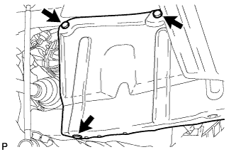
Install the flywheel housing under cover.
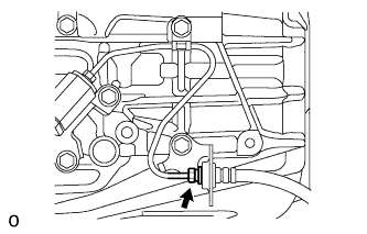
| 33. INSTALL PROPELLER WITH CENTER BEARING SHAFT ASSEMBLY (for 4WD) |
Install the propeller shaft assembly (RAV4_ACA30 RM00000226E001X.html).
| 34. CONNECT HEATED OXYGEN SENSOR (for 4WD) |
- NOTICE:
- Do not strike the metal part of the sensor.
Rotate the sensor counterclockwise the same number of times as recorded in the removal procedure, and then connect it to the front exhaust pipe by hand.
- NOTICE:
- After rotating the sensor counterclockwise the same number of times as in the removal procedure, connect it while making sure that the wire harness is not twisted.
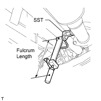
Using SST, tighten the sensor.
- SST
- 09224-00010
- Torque:
- with SST:
- 40 N*m{408 kgf*cm, 30 ft.*lbf}
- without SST:
- 44 N*m{449 kgf*cm, 32 ft.*lbf}
- HINT:
- Make sure SST and the wrench are connected in a straight line.
- Use a torque wrench with a fulcrum length of 300 mm (11.8 in.).
 |
Connect the grommet to the floor panel.
| 35. INSTALL FRONT EXHAUST PIPE ASSEMBLY |
Using a vernier caliper, measure the free length of the compression springs.
- Minimum Free Length:
- 41.5 mm (1.63 in.)
 |
Install a new gasket by hand so that its surface is flush with the exhaust manifold.
- NOTICE:
- Make sure the gasket is facing the correct direction.
- Do not reuse the removed gasket.
- Do not push in the gasket while installing the front exhaust pipe.
 |
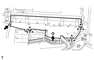
Install the front exhaust pipe and 2 compression springs with the 2 bolts.
- Torque:
- 43 N*m{438 kgf*cm, 32 ft.*lbf}
 |
Install a new gasket to the front exhaust pipe.
Connect the front exhaust pipe to the center exhaust pipe with the 2 bolts.
- Torque:
- 43 N*m{438 kgf*cm, 32 ft.*lbf}
 |
| 36. INSTALL DRIVE SHAFT |
for 2WD:
Install the front drive shafts (RAV4_ACA30 RM00000226J015X.html).
for 4WD:
Install the front drive shafts (RAV4_ACA30 RM00000226O008X.html).
| 37. INSTALL FRONT AXLE HUB SUB-ASSEMBLY LH |
Install the front axle hub sub-assembly (RAV4_ACA30 RM00000227H00JX.html).
| 38. INSTALL FRONT AXLE HUB SUB-ASSEMBLY RH |
- HINT:
- Perform the same procedures described for the LH side.
| 39. INSTALL FRONT AXLE SHAFT NUT LH |
Clean the threaded parts on the drive shaft and a new axle shaft nut using a non-residue solvent.
- NOTICE:
- Be sure to perform this work for a new drive shaft.
- Keep the threaded parts free of oil and foreign objects.
Install a new shaft nut.
- Torque:
- for φ 26:
- 216 N*m{2203 kgf*cm, 159 ft.*lbf}
- for φ 30:
- 292 N*m{2978 kgf*cm, 215 ft.*lbf}
Using a chisel and hammer, stake the shaft nut.
 |
| 40. INSTALL FRONT AXLE SHAFT NUT RH |
- HINT:
- Perform the same procedures described for the LH side.
| 41. CONNECT NO. 1 STEERING COLUMN HOLE COVER SUB-ASSEMBLY |
Attach clip B to the body portion and connect the No. 1 steering column hole cover to the body portion with clip A.
- NOTICE:
- Make sure that the lip portion of the No. 1 steering column hole cover is not damaged.
 |
| 42. CONNECT NO. 2 STEERING INTERMEDIATE SHAFT ASSEMBLY |
 |
Align the matchmarks and install the No. 2 steering intermediate shaft to the steering intermediate shaft.
- Torque:
- 35 N*m{360 kgf*cm, 26 ft.*lbf}
| 43. INSTALL COLUMN HOLE COVER SILENCER SHEET |
 |
Install the silencer sheet with the 2 clips.
Install the floor carpet.
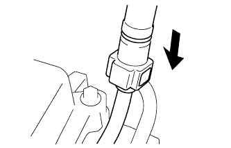
| 44. CONNECT CLUTCH TUBE (for Manual Transaxle) |
Connect the clutch hose and install the clip to the clutch hose.
- NOTICE:
- Install the clip as far as it will go.
 |
Using a 10 mm union nut wrench, connect the clutch hose to the flexible hose tube while holding the flexible hose.
- Torque:
- 15 N*m{155 kgf*cm, 11 ft.*lbf}
- NOTICE:
- Use the formula to calculate special torque values for situations where a union nut wrench is combined with a torque wrench (RAV4_ACA30 RM0000018UO018X.html).
- Do not kink or damage the clutch release cylinder tube.
- Do not allow any foreign matter such as dirt or dust to enter the clutch release cylinder tube from the clip or bracket.
- This torque value is effective when the union nut wrench is parallel to the torque wrench.
| 45. CONNECT TRANSMISSION CONTROL CABLE ASSEMBLY (for CVT) |
Connect the clamp of the control cable with the bolt.
- Torque:
- 5.0 N*m{51 kgf*cm, 44 in.*lbf}
 |
Connect the transmission control cable to the control cable support.
 |
Connect the transmission control cable to the bracket with a new clip.
 |
Connect the transmission control cable to the control shaft lever with the nut.
- Torque:
- 12 N*m{122 kgf*cm, 9 ft.*lbf}
| 46. CONNECT TRANSMISSION CONTROL CABLE ASSEMBLY (for Manual Transaxle) |
Connect the control cable to the control cable bracket, and install 2 new clips.
 |
Connect the control cable to the transaxle, and install the 2 washers and 2 clips.
 |
| 47. CONNECT WIRE HARNESS AND HOSE |
Connect the heater hoses.
 |
Connect the connector tube hose.
 |
Install the ground wire with the bolt and clamp.
- Torque:
- 19 N*m{194 kgf*cm, 14 ft.*lbf}
 |
Connect the engine wire and install the nut.
- Torque:
- 13 N*m{130 kgf*cm, 9 ft.*lbf}
 |
Connect the 3 relay block connectors.
Connect the engine wire with the 2 clamps and install the bolt.
- Torque:
- 7.7 N*m{79 kgf*cm, 68 in.*lbf}
 |
| 48. CONNECT FUEL TUBE SUB-ASSEMBLY |
Push the tube connector onto the pipe until the tube connector makes a "click" sound.
- NOTICE:
- Before connecting the connector and fuel pipe, check that there is no damage or foreign matter on the connecting part of the fuel pipe.
- After connecting the fuel tube connector and pipe, check that they are securely connected by trying to pull them apart.
 |
Install the No. 1 fuel pipe clamp.
Text in Illustration *1 No. 1 Fuel Pipe Clamp
 |
| 49. CONNECT NO. 1 RADIATOR HOSE |
Connect the radiator hose to the cylinder head.
- HINT:
- The direction of the hose clamp is indicated in the illustration.
 |
| 50. INSTALL ECM |
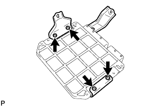
Install the 2 brackets to the ECM with the 4 screws.
- Torque:
- 3.0 N*m{30 kgf*cm, 27 in.*lbf}
 |
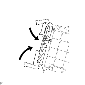
Connect the 2 ECM connectors.
- NOTICE:
- When connecting the connector, make sure that dirt, water and other foreign matter does not become stuck between the connector and the other part.
Connect the 2 ECM connectors and lower the 2 levers.
- NOTICE:
- Make sure that the 2 levers are securely lowered.
 |
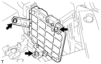
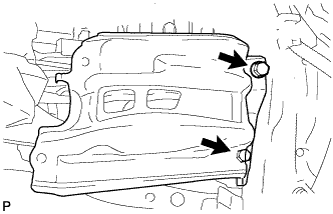
Install the ECM with the 3 bolts.
- Torque:
- 6.5 N*m{66 kgf*cm, 57 in.*lbf}
 |
| 51. INSTALL AIR CLEANER CASE |
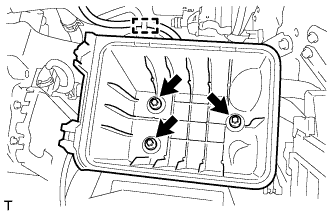
Install the air cleaner case with the 3 bolts.
- Torque:
- 5.0 N*m{51 kgf*cm, 44 in.*lbf}
 |
Attach the wire harness clamp to the air cleaner case.
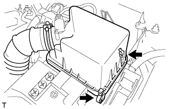
| 52. INSTALL AIR CLEANER CAP SUB-ASSEMBLY |
Insert the hinge part of the air cleaner cap and hose into the air cleaner case, and then fasten the 2 hook clamps.
 |
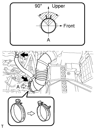
Connect the No. 1 air cleaner hose to the throttle body and push apart the tabs of the No. 1 air cleaner hose clamp.
- HINT:
- The direction of the hose clamp is indicated in the illustration.
 |
Connect the No. 2 ventilation hose to the cylinder head cover.
Attach the clamp.
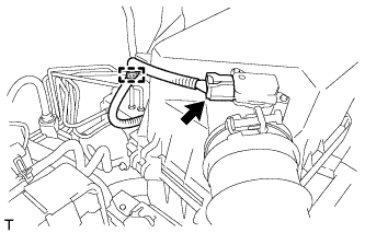 |
Connect the mass air flow meter connector.
| 53. INSTALL BATTERY BRACKET REINFORCEMENT |
Install the battery bracket reinforcement with the 2 bolts.
- Torque:
- 20 N*m{204 kgf*cm, 15 ft.*lbf}
 |
| 54. INSTALL FRONT BATTERY BRACKET |
Install the front battery bracket with the 3 bolts.
- Torque:
- 20 N*m{204 kgf*cm, 15 ft.*lbf}
 |
Connect the No. 3 engine wire with the bolt.
- Torque:
- 20 N*m{204 kgf*cm, 15 ft.*lbf}
Attach the 3 wire harness clamps.
| 55. INSTALL BATTERY TRAY |
| 56. INSTALL BATTERY |
| 57. INSTALL BATTERY CLAMP SUB-ASSEMBLY |
Attach the hook of the battery clamp to the front battery bracket.
 |
Partially tighten the nut and temporarily install the bolt.
Adjust the battery clamp position.
Tighten the nut and bolt.
- Torque:
- for bolt:
- 17 N*m{168 kgf*cm, 12 ft.*lbf}
- for nut:
- 4.9 N*m{50 kgf*cm, 43 in.*lbf}
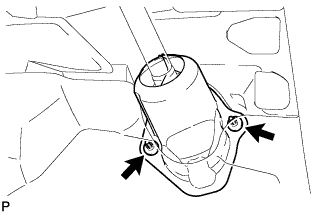
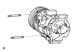
| 58. CONNECT COMPRESSOR WITH PULLEY ASSEMBLY (w/ Air Conditioning System) |
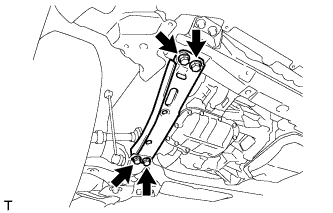
Connect the compressor with pulley assembly with the 2 stud bolts.
- Torque:
- 9.8 N*m{100 kgf*cm, 87 in.*lbf}
 |
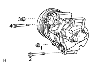
Install the 2 bolts and 2 nuts.
- Torque:
- 25 N*m{255 kgf*cm, 18 ft.*lbf}
- NOTICE:
- Tighten the bolts and the nuts in the order shown in the illustration.
 |
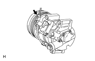
Connect the connector.
 |
| 59. CONNECT NO. 2 RADIATOR HOSE |
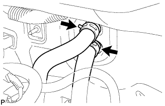
Align the paint mark of the radiator hose with the triangle mark of the water inlet and connect the radiator hose to the water inlet.
Text in Illustration *1 Paint Mark *2 Triangle Mark - HINT:
- Be sure to align the pinching portion of the hose clamp with the triangle mark of the water inlet.
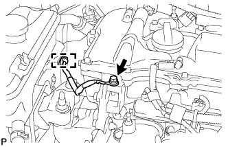
 |
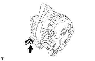
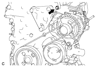
| 60. INSTALL GENERATOR ASSEMBLY |
Install the wire harness clamp bracket with the bolt.
- Torque:
- 8.4 N*m{85 kgf*cm, 74 in.*lbf}
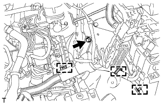
 |
Temporarily install the generator with the bolt.
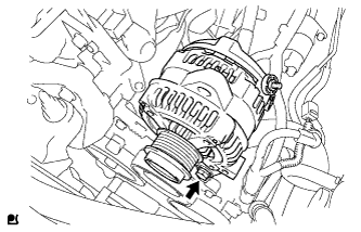 |
Temporarily install the adjusting bar with the 2 bolts.
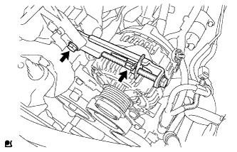 |
Install the wire harness to terminal B with the nut.
- Torque:
- 9.8 N*m{100 kgf*cm, 87 in.*lbf}
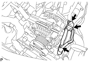 |
Install the terminal cap.
Connect the connector and wire harness clamp.
Install V-ribbed belt (RAV4_ACA30 RM0000027IM00YX_03_0012.html).
Adjust V-ribbed belt (RAV4_ACA30 RM0000027IM00YX_03_0013.html).
Inspect V-ribbed belt (RAV4_ACA30 RM000003V6X004X_01_0001.html).
Tighten the bolt.
- Torque:
- 19 N*m{189 kgf*cm, 14 ft.*lbf}
 |
| 61. INSTALL V-RIBBED BELT |
Temporarily install the V-ribbed belt.
| 62. ADJUST V-RIBBED BELT |
Turn bolt C to adjust the tension of the V-ribbed belt.
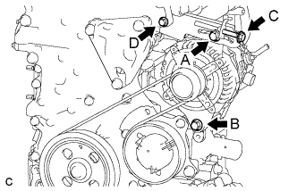 |
Tighten bolts A and B.
- Torque:
- for bolt A:
- 19 N*m{189 kgf*cm, 14 ft.*lbf}
- for bolt B:
- 43 N*m{438 kgf*cm, 32 ft.*lbf}
- NOTICE:
- Do not loosen bolt D.
| 63. CONNECT RADIATOR RESERVOIR ASSEMBLY |
Connect the radiator reservoir with the 2 bolts.
- Torque:
- 5.0 N*m{51 kgf*cm, 44 in.*lbf}
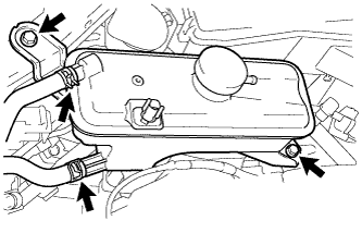 |
Connect the No. 1 and No. 2 water by-pass hoses.
| 64. CONNECT CABLE TO NEGATIVE BATTERY TERMINAL |
| 65. ADD TRANSFER OIL (for 4WD) |
Remove the case plug (for filler) and gasket.
Pour oil so that the oil level is between 0 to 5.0 mm (0 to 0.197 in.) from the bottom lip of the case plug (for filler) hole.
- NOTICE:
- When adding oil, pour it slowly.
- Add oil a little at a time, waiting several minutes between each addition of oil.
Wait approximately 5 minutes and check that the oil level has not changed.
Install a new gasket and the case plug (for filler).
- Torque:
- 39 N*m{398 kgf*cm, 28 ft.*lbf}
| 66. ADD CONTINUOUSLY VARIABLE TRANSAXLE FLUID (for CVT) |
Add continuously variable transaxle fluid (RAV4_ACA30 RM0000013BU03VX.html).
| 67. ADD MANUAL TRANSAXLE OIL (for Manual Transaxle) |
Add oil until the oil level is within 5 mm (0.197 in.) from the bottom of the transmission filler plug opening.
 |
Install a new gasket and the transmission filler plug.
- Torque:
- 39 N*m{400 kgf*cm, 29 ft.*lbf}
- NOTICE:
- When adding transaxle oil, make sure the vehicle is level.
- An excessively large or small amount of oil may cause problems.
- After adding oil, drive the vehicle and recheck the oil level.
| 68. ADD ENGINE OIL |
Clean and install the oil pan drain plug together with a new gasket.
- Torque:
- 37 N*m{377 kgf*cm, 27 ft.*lbf}
Add new engine oil.
- Standard Oil Grade:
Oil Grade Oil Viscosity (SAE) API grade SL or SM multigrade engine oil - 15W-40
- 20W-50
API grade SL "Energy-Conserving", SM "Energy-Conserving" or ILSAC multigrade engine oil - 0W-20
- 5W-20
- 5W-30
- 10W-30
- 15W-40
- Standard Capacity:
Item Specified Condition Drain and refill without oil filter change 3.9 liters (4.1 US qts, 3.4 Imp. qts) Drain and refill with oil filter change 4.2 liters (4.4 US qts, 3.7 Imp. qts) Dry fill 4.7 liters (5.0 US qts, 4.1 Imp. qts)
Install the oil filler cap.
| 69. ADD ENGINE COOLANT |
Tighten the radiator drain cock plug by hand.
Tighten the water drain cock plug.
- Torque:
- 13 N*m{130 kgf*cm, 9 ft.*lbf}
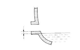
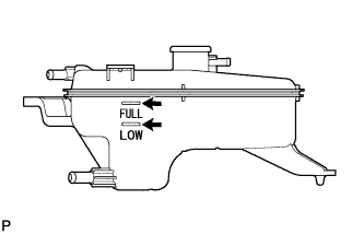
Add TOYOTA Super Long Life Coolant (SLLC) to the radiator reservoir filler opening until it is filled to the B line at the base of the reservoir filler neck.
- HINT:
- The B line is the lower edge of the inner wall of the filler neck.
- Standard capacity:
Item Specified Condition for Manual Transaxle 5.8 liters (6.1 US qts, 5.1 Imp. qts) for CVT 6.0 liters (6.3 US qts, 5.3 Imp. qts)
- HINT:
- TOYOTA vehicles are filled with TOYOTA SLLC at the factory. In order to avoid damage to the engine cooling system and other technical problems, only use TOYOTA SLLC or similar high quality ethylene glycol based non-silicate, non-amine, non-nitrite, non-borate coolant with long-life hybrid organic acid technology (coolant with long-life hybrid organic acid technology is a combination of low phosphates and organic acids).
- NOTICE:
- Never use water as a substitute for engine coolant.
 |
Press the No. 1 and No. 2 radiator hoses several times by hand, and then check the level of the coolant. If the coolant level drops below the B line, add TOYOTA SLLC to the B line.
Install the radiator reservoir cap.
Start the engine and warm it up until the cooling fan operates.
Set the air conditioning as follows while warming up the engine.
Measurement condition Item Condition Manual Air Conditioning System Fan speed: Any setting except off
Temperature: Toward WARM
Air conditioning switch: OffAutomatic Air Conditioning System Temperature: Toward MAX (HOT)
Air conditioning switch: OffMaintain the engine speed at 2000 to 2500 rpm and warm up the engine until the cooling fan operates.
- NOTICE:
- Make sure that the radiator reservoir still has some coolant in it.
- Pay attention to the needle of the coolant temperature meter. Make sure that the needle does not show an abnormally high temperature.
- If there is not enough coolant, the engine may burn out or overheat.
- After starting the engine, if the radiator reservoir does not have any coolant, perform the following: 1) stop the engine, 2) wait until the coolant has cooled down, and 3) add coolant until the coolant is filled to the B line.
- Run the engine at 2000 rpm until the coolant level has stabilized.
Press the No. 1 and No. 2 radiator hoses several times by hand to bleed air.
- CAUTION:
- When pressing the radiator hoses:
- Wear protective gloves.
- Be careful as the radiator hoses are hot.
- Keep your hands away from the radiator fan.
Stop the engine and wait until the coolant cools down to ambient temperature.
Check that the coolant level is between the FULL and LOW lines. If the coolant level is below the LOW line, repeat all of the procedures above.
If the coolant level is above the FULL line, drain coolant so that the coolant level is between the FULL and LOW lines.
 |
| 70. INSPECT SHIFT LEVER POSITION (for CVT) |
When moving the shift lever from P to R with the ignition switch ON and the brake pedal depressed, make sure that the shift lever moves smoothly and correctly into position.
Start the engine and make sure that the vehicle moves forward after moving the shift lever from N to D and moves in reverse after moving the shift lever to R.
If the operation cannot be performed as specified, inspect the park/neutral position switch assembly and check the shift lever assembly installation condition.
| 71. INSPECT FOR FUEL LEAK |
Make sure that there are no fuel leaks after performing maintenance on the fuel system.
Connect the intelligent tester to the DLC3.
Turn the ignition switch to ON, and push the intelligent tester main switch on.
- NOTICE:
- Do not start the engine.
Enter the following menus: Powertrain / Engine and ECT / Active Test / Control the Fuel Pump / Speed.
Check that there are no leaks from the fuel system.
Turn the ignition switch off.
Disconnect the intelligent tester from the DLC3.
| 72. INSPECT FOR OIL LEAK |
Start the engine. Make sure that there are no oil leaks from the areas that were worked on.
| 73. INSPECT FOR COOLANT LEAK |
Remove the radiator reservoir cap.
- CAUTION:
- To avoid the danger of being burned, do not remove the radiator reservoir cap while the engine and radiator are still hot. Thermal expansion will cause hot engine coolant and steam to blow out from the radiator reservoir.
Fill the radiator and reservoir with coolant, and then attach a radiator cap tester.
 |
Warm up the engine.
Pump the radiator cap tester to 118 kPa (1.2 kgf/cm2, 17.1 psi), and then check that the pressure does not drop.
If the pressure drops, check the hoses, radiator and water pump for leakage.
If there are no signs of external coolant leaks, check the heater core, cylinder block and head.
Reinstall the radiator reservoir cap.
| 74. INSPECT IGNITION TIMING |
Warm up and stop the engine.
When using an intelligent tester:
Connect the intelligent tester to the DLC3.
Start the engine and idle it.
Turn the intelligent tester main switch on.
Enter the following menus: Powertrain / Engine and ECT / Data List / IGN Advance.
- Standard ignition timing:
- 8 to 12° BTDC @ idle
- HINT:
- Refer to the intelligent tester operator's manual for further details.
- NOTICE:
- Turn all the electrical systems and the A/C off.
- Check the ignition timing with the cooling fan off.
- When checking the ignition timing, the shift lever should be in neutral or P (for CVT).
When not using the intelligent tester:
Remove the No. 2 cylinder head cover.
Connect the tester probe of a timing light to the wire of the ignition coil connector for the No. 1 cylinder.
- NOTICE:
- Use a timing light that detects primary signals.
Start the engine and idle it.
Using SST, connect terminals 13 (TC) and 4 (CG) of the DLC3.
Text in Illustration *1 Front view of DLC3 - SST
- 09843-18040
- NOTICE:
- Confirm the terminal numbers before connecting them. Connecting the wrong terminals can damage the engine.
- When checking the ignition timing, the shift lever should be in neutral or P (for CVT).
Using the timing light, check the ignition timing.
- Standard ignition timing:
- 8 to 12° BTDC @ idle
- NOTICE:
- Turn all the electrical systems and the A/C off.
- Check the ignition timing with the cooling fan off.
- When checking the ignition timing, the shift lever should be in neutral or P (for CVT).
Remove SST from the DLC3.
Check that the ignition timing advances immediately when the engine speed is increased.
Turn the ignition switch off.
Remove the timing light.
Install the No. 2 cylinder head cover.

| 75. INSPECT ENGINE IDLE SPEED |
Warm up and stop the engine.
When using the intelligent tester:
Connect the intelligent tester to the DLC3.
Turn the ignition switch to ON.
Enter the following menus: Powertrain / Engine and ECT / Data List / Engine Speed.
- Standard Idle Speed:
Item Specified Condition for Manual Transaxle 580 to 680 rpm for CVT 600 to 700 rpm
- HINT:
- Refer to the intelligent tester operator's manual for further details.
- NOTICE:
- Turn all the electrical systems and the A/C off.
- Check the ignition timing with the cooling fan off.
- When checking the idling speed, the shift lever should be in neutral or P (for CVT).
Turn the ignition switch off.
Disconnect the intelligent tester from the DLC3.
When not using the intelligent tester:
Text in Illustration *1 Front view of DLC3 Using SST, connect a tachometer probe to terminal 9 (TAC) of the DLC3.
- SST
- 09843-18030
- NOTICE:
- Confirm the terminal numbers before connecting them. Connecting the wrong terminals can damage the engine.
- When checking the idling speed, the shift lever should be in neutral or P (for CVT).
Check the idle speed.
- Standard Idle Speed:
Item Specified Condition for Manual Transaxle 580 to 680 rpm for CVT 600 to 700 rpm
Disconnect the tachometer probe from the DLC3.
 |
| 76. INSPECT CO/HC |
Start the engine.
Run the engine at 2500 rpm for approximately 180 seconds.
Insert the CO/HC meter testing probe at least 40 cm (1.31 ft.) into the tailpipe while idling.
Check the CO/HC concentration during idling and when the engine is running at 2500 rpm.
- HINT:
- When doing the 2 mode (with the engine idling/ running at 2500 rpm) test, the measuring procedures are determined by applicable local regulations.
- If the CO/HC concentration does not comply with the regulations, troubleshoot in the order given below.
Check the air fuel ratio sensor (RAV4_ACA30 RM000002WUP024X_01_0001.html) and heated oxygen sensor operation (RAV4_ACA30 RM000001Z1X00WX.html).
See the table below for possible causes, and then inspect the applicable parts and repair them if necessary.
CO HC Problems Possible Causes Normal High Rough idling - Faulty ignition:
- Incorrect timing
- Plugs are contaminated or shorted, or gaps are defective
- Incorrect valve clearance
- Leakage from intake or exhaust valves
- Leakage from cylinders
Low High Rough idling
(Fluctuating HC reading)- Vacuum leaks:
- PCV hoses
- Intake manifold
- Throttle body
- Brake booster line
- Lean mixture causing misfire
High High Rough idling
(Black smoke from exhaust)- Restricted air cleaner filter element
- Plugged PCV valve
- Faulty SFI system:
- Faulty pressure regulator
- Faulty engine coolant temperature sensor
- Faulty mass air flow meter
- Faulty ECM
- Faulty injectors
- Faulty throttle body
- Faulty ignition:
| 77. INSTALL FRONT WHEEL |
- Torque:
- 103 N*m{1050 kgf*cm, 76 ft.*lbf}
| 78. ADJUST WHEEL ALIGNMENT |
Adjust the front wheel alignment (RAV4_ACA30 RM00000227W003X.html).
| 79. INSTALL FRONT FLOOR COVER |
Install the floor under cover with the 3 clips, bolt and nut.
- Torque:
- for bolt:
- 12 N*m{122 kgf*cm, 9 ft.*lbf}
- for nut:
- 6.0 N*m{61 kgf*cm, 53 in.*lbf}
 |
| 80. INSTALL NO. 2 ENGINE UNDER COVER |
Install the under cover with the 3 clips.
 |
| 81. INSTALL REAR ENGINE UNDER COVER RH |
Install the under cover with the 3 clips.
 |
| 82. INSTALL REAR ENGINE UNDER COVER LH |
Install the under cover with the 2 clips.
 |
| 83. INSTALL NO. 1 ENGINE UNDER COVER |
Install the under cover with the 6 screws and 10 clips.
 |
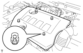
| 84. INSTALL NO. 2 CYLINDER HEAD COVER |
Attach the 4 clips to install the cover.
- NOTICE:
- Be sure to attach the clips securely.
- Do not apply excessive force or do not hit the cover to attach the clips. This may cause the cover to break.
 |
| 85. INSTALL RADIATOR SUPPORT OPENING COVER |
Install the radiator support opening cover with the 9 clips.
| 86. RESET MEMORY |
When replacing the engine assembly, perform the Reset Memory procedure (CVT initialization) for K111 (RAV4_ACA30 RM000003UQR002X.html).