Dtc B15C0 Short In Gps Antenna
DESCRIPTION
WIRING DIAGRAM
INSPECTION PROCEDURE
CLEAR DTC
CHECK FOR DTC
CHECK HARNESS AND CONNECTOR
CHECK NAVIGATION ANTENNA CORD SUB-ASSEMBLY
REPLACE NAVIGATION ANTENNA ASSEMBLY
REPLACE INSTRUMENT PANEL INTEGRATION ANTENNA ASSEMBLY
REPLACE DIVIDER ANTENNA ASSEMBLY
DTC B15C0 Short in GPS Antenna |
DTC B15C1 Open in GPS Antenna |
DESCRIPTION
This DTC is stored when a malfunction occurs in the navigation antenna assembly.DTC Code
| DTC Detection Condition
| Trouble Area
|
B15C0
| A GPS antenna error.
| - Navigation antenna assembly (w/o Blocking System)
- Navigation antenna cord sub-assembly (w/o Blocking System)
- Instrument panel integration antenna assembly (w/ Blocking System)
- Divider antenna assembly (w/ Blocking System)
- Navigation receiver assembly
|
B15C1
| An error of the power source to the GPS antenna.
| - Navigation antenna assembly (w/o Blocking System)
- Navigation antenna cord sub-assembly (w/o Blocking System)
- Instrument panel integration antenna assembly (w/ Blocking System)
- Divider antenna assembly (w/ Blocking System)
- Navigation receiver assembly
|
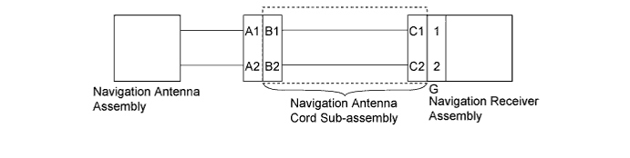
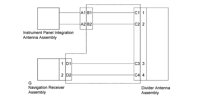
WIRING DIAGRAM
INSPECTION PROCEDURE
Clear the DTCs (HILUX_TGN26 RM0000011BU0LCX.html).
Check for DTCs and check if the same trouble occurs again.
- OK:
- No DTCs are output.
| 3.CHECK HARNESS AND CONNECTOR |
- *1: w/o Blocking System
- *2: w/ Blocking System
Check if the navigation antenna assembly*1 or instrument panel integration antenna assembly*2 is securely connected to the navigation receiver assembly.
- OK:
- Navigation antenna assembly*1 or instrument panel integration antenna assembly*2 is securely connected.
ResultResult
| Proceed to
|
OK (w/o Blocking System)
| A
|
OK (w/ Blocking System)
| B
|
NG
| C
|
| |
|
| | SECURELY CONNECT NAVIGATION ANTENNA ASSEMBLY |
|
|
| 4.CHECK NAVIGATION ANTENNA CORD SUB-ASSEMBLY |
Disconnect the A navigation antenna assembly connector.
Disconnect the G navigation receiver assembly connector.
Measure the resistance according to the value(s) in the table below.
- Standard Resistance:
Tester Connection
| Condition
| Specified Condition
|
A (Core wire) - B (Core wire)
| Always
| Below 1 Ω
|
A (Shield) - B (Shield)
| Always
| Below 1 Ω
|
A (Core wire) - A (Shield) or B (Core wire) - B (Shield)
| Always
| 10 kΩ or higher
|
Text in Illustration*a
| Component without harness connected
(Navigation antenna cord sub-assembly)
|
*1
| Core wire
|
*2
| Shield
|
| 5.REPLACE NAVIGATION ANTENNA ASSEMBLY |
Temporarily replace the navigation antenna assembly with a new or normally functioning one (HILUX_TGN26 RM000003O1I009X.html).
Clear the DTCs (HILUX_TGN26 RM0000011BU0LCX.html).
Recheck for DTCs and check if the same trouble occurs again.
- OK:
- No DTCs are output.
| OK |
|
|
|
| END (NAVIGATION ANTENNA ASSEMBLY IS DEFECTIVE) |
|
| 6.REPLACE INSTRUMENT PANEL INTEGRATION ANTENNA ASSEMBLY |
Temporarily replace the instrument panel integration antenna assembly with a new or normally functioning one.
Clear the DTCs (HILUX_TGN26 RM0000011BU0LCX.html).
Recheck for DTCs and check if the same trouble occurs again.
- OK:
- No DTCs are output.
| OK |
|
|
|
| END (INSTRUMENT PANEL INTEGRATION ANTENNA ASSEMBLY IS DEFECTIVE) |
|
| 7.REPLACE DIVIDER ANTENNA ASSEMBLY |
Temporarily replace the divider antenna assembly with a new or normally functioning one.
Clear the DTCs (HILUX_TGN26 RM0000011BU0LCX.html).
Recheck for DTCs and check if the same trouble occurs again.
- OK:
- No DTCs are output.
| | REPAIR OR REPLACE HARNESS OR CONNECTOR |
|
|
| OK |
|
|
|
| END (DIVIDER ANTENNA ASSEMBLY IS DEFECTIVE) |
|