Automatic Transmission System (For 1Kd-Ftv With I-Art) L4 Position Switch Circuit
Drivetrain. Hilux. Tgn26, 36 Kun25, 26, 35, 36 Ggn25
DESCRIPTION
WIRING DIAGRAM
INSPECTION PROCEDURE
CHECK HARNESS AND CONNECTOR (NO. 1 TRANSFER INDICATOR SWITCH - BODY GROUND)
INSPECT NO. 1 TRANSFER INDICATOR SWITCH
CHECK HARNESS AND CONNECTOR (NO. 1 TRANSFER INDICATOR SWITCH - TCM)
AUTOMATIC TRANSMISSION SYSTEM (for 1KD-FTV with i-ART) - L4 Position Switch Circuit |
DESCRIPTION
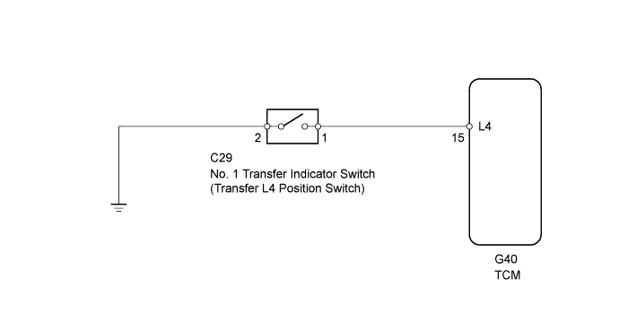
The No. 1 transfer indicator switch (the transfer L4 position switch) detects the gear position of the transfer shift lever. Moving the transfer shift lever to L4 turns the No. 1 transfer indicator switch (the transfer L4 position switch) on. Then the TCM cancels operation of the lock-up clutch.
WIRING DIAGRAM
INSPECTION PROCEDURE
| 1.CHECK HARNESS AND CONNECTOR (NO. 1 TRANSFER INDICATOR SWITCH - BODY GROUND) |
Disconnect the No. 1 transfer indicator switch connector.
Measure the resistance according to the value(s) in the table below.
- Standard Resistance:
Tester Connection
| Condition
| Specified Condition
|
C29-2 - Body ground
| Always
| Below 1 Ω
|
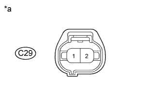
Text in Illustration*a
| Front view of wire harness connector
(to No. 1 Transfer Indicator Switch)
|
| | REPAIR OR REPLACE HARNESS AND CONNECTOR |
|
|
| 2.INSPECT NO. 1 TRANSFER INDICATOR SWITCH |
Remove the No. 1 transfer indicator switch.
Measure the resistance according to the value(s) in the table below.
- Standard Resistance:
Tester Connection
| Switch Condition
| Specified Condition
|
1 - 2
| Not pushed
| 10 kΩ or higher
|
1 - 2
| Pushed
| Below 1 Ω
|
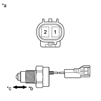
Text in Illustration*a
| Component without harness connected
(No. 1 Transfer Indicator Switch)
|
*b
| Pushed
|
*c
| Not pushed
|
| 3.CHECK HARNESS AND CONNECTOR (NO. 1 TRANSFER INDICATOR SWITCH - TCM) |
Disconnect the C29 No. 1 transfer indicator switch connector.
Disconnect the G40 TCM connector.
Measure the resistance according to the value(s) in the table below.
- Standard Resistance:
Tester Connection
| Condition
| Specified Condition
|
C29-1 - G40-15 (L4)
| Always
| Below 1 Ω
|
C29-1 or G40-15 (L4) - Body ground
| Always
| 10 kΩ or higher
|
| | REPAIR OR REPLACE HARNESS AND CONNECTOR |
|
|