Dtc B279A Theft Deterrent System Communication Line High Fixation
DESCRIPTION
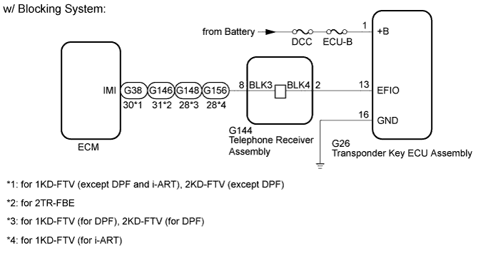
WIRING DIAGRAM
INSPECTION PROCEDURE
CLEAR DTC
CHECK FOR DTC
CHECK HARNESS AND CONNECTOR (SFI OR ECD COMMUNICATION LINE)
CHECK TRANSPONDER KEY ECU ASSEMBLY (TERMINAL EFIO)
CHECK HARNESS AND CONNECTOR (TRANSPONDER KEY ECU - BATTERY AND BODY GROUND)
REPLACE ECM
REGISTER ECU COMMUNICATION ID
CLEAR DTC
CHECK FOR DTC
REPLACE TRANSPONDER KEY ECU ASSEMBLY
REGISTER ECU COMMUNICATION ID
CLEAR DTC
CHECK FOR DTC
DTC B279A Theft Deterrent System Communication Line High Fixation |
DESCRIPTION
If the communication line (EFIO-IMI) to the transponder key ECU assembly is stuck on HI output, the ECM stores this DTC.DTC Code
| DTC Detection Condition
| Trouble Area
| DTC Output Confirmation Operation
|
B279A
| The communication line (EFIO-IMI) between the ECM and transponder key ECU assembly is stuck on HI output (1 trip detection logic*1).
| - Harness or connector
- Transponder key ECU assembly
- ECM
- Telephone transceiver assembly*2
| Turn the ignition switch to ON and wait 6 seconds.
|
- *1: Only output while a malfunction is present.
- *2: w/ Blocking System
Vehicle Condition and Fail-safe Operation when Malfunction DetectedVehicle Condition when Malfunction Detected
| Fail-safe Operation when Malfunction Detected
|
Engine cannot be started (initial ignition occurs and engine cranks, then ignition stop).
| Engine cannot be started.
|
Related Data List and Active TestDTC Code
| Data List and Active Test
|
B279A
| -
|
WIRING DIAGRAM
INSPECTION PROCEDURE
- NOTICE:
- When replacing the transponder key ECU assembly, ECM or telephone transceiver assembly (w/ Blocking System), refer to the Service Bulletin.
- After performing repairs, perform the operation that fulfills the DTC output confirmation operation, and then confirm that no DTCs are output again.
- Inspect the fuses for circuits related to this system before performing the following inspection procedure.
- HINT:
- w/ Blocking System:
- After troubleshooting for this DTC, make sure B279A is not present. If present, troubleshoot the blocking system DTCs next.
Clear the DTCs (HILUX_TGN26 RM000000Z3I00TX.html).
Check for DTCs (HILUX_TGN26 RM000000Z3I00TX.html).
ResultResult
| Proceed to
|
No DTC is output
| A
|
DTC B279A and other DTCs are output
| B
|
DTC B279A is output
| C
|
- HINT:
- If any DTCs other than B279A are output, troubleshoot those DTCs first.
| 3.CHECK HARNESS AND CONNECTOR (SFI OR ECD COMMUNICATION LINE) |
Disconnect the G26 transponder key ECU assembly connector.
Disconnect the G38*1, G88*2, G146*3, G148*4 or G156*5ECM connector.
- *1: for 1KD-FTV (except DPF and i-ART), 2KD-FTV (except DPF)
- *2: for 2TR-FE
- *3: for 2TR-FBE
- *4: for 1KD-FTV (for DPF), 2KD-FTV (for DPF)
- *5: 1KD-FTV (for i-ART)
w/ Blocking System:
Disconnect the G144 telephone transceiver assembly connector.
Measure the resistance according to the value(s) in the table below.
- Standard Resistance:
- for 1KD-FTV (except DPF and i-ART), 2KD-FTV (except DPF) [w/o Blocking System]:
Tester Connection
| Condition
| Specified Condition
|
G26-13 (EFIO) - G38-30 (IMI)
| Always
| Below 1 Ω
|
G26-13 (EFIO) or G38-30 (IMI) - Body ground
| Always
| 10 kΩ or higher
|
- for 1KD-FTV (except DPF and i-ART), 2KD-FTV (except DPF) [w/ Blocking System]:
Tester Connection
| Condition
| Specified Condition
|
G26-13 (EFIO) - G144-2 (BLK4)
| Always
| Below 1 Ω
|
G144-8 (BLK3) - G38-30 (IMI)
| Always
| Below 1 Ω
|
G26-13 (EFIO) or G144-2 (BLK4) - Body ground
| Always
| 10 kΩ or higher
|
G144-8 (BLK3) or G38-30 (IMI) - Body ground
| Always
| 10 kΩ or higher
|
- for 2TR-FE:
Tester Connection
| Condition
| Specified Condition
|
G26-13 (EFIO) - G88-16 (IMI)
| Always
| Below 1 Ω
|
G26-13 (EFIO) or G88-16 (IMI) - Body ground
| Always
| 10 kΩ or higher
|
- for 2TR-FBE (w/o Blocking System):
Tester Connection
| Condition
| Specified Condition
|
G26-13 (EFIO) - G146-31 (IMI)
| Always
| Below 1 Ω
|
G26-13 (EFIO) or G146-31 (IMI) - Body ground
| Always
| 10 kΩ or higher
|
- for 2TR-FBE (w/ Blocking System):
Tester Connection
| Condition
| Specified Condition
|
G26-13 (EFIO) - G144-2 (BLK4)
| Always
| Below 1 Ω
|
G144-8 (BLK3) - G146-31 (IMI)
| Always
| Below 1 Ω
|
G26-13 (EFIO) or G144-2 (BLK4) - Body ground
| Always
| 10 kΩ or higher
|
G144-8 (BLK3) or G146-31 (IMI) - Body ground
| Always
| 10 kΩ or higher
|
- for 1KD-FTV (for DPF), 2KD-FTV (for DPF) [w/o Blocking System]:
Tester Connection
| Condition
| Specified Condition
|
G26-13 (EFIO) - G148-28 (IMI)
| Always
| Below 1 Ω
|
G26-13 (EFIO) or G148-28 (IMI) - Body ground
| Always
| 10 kΩ or higher
|
- for 1KD-FTV (except DPF and i-ART), 2KD-FTV (except DPF) [w/ Blocking System]:
Tester Connection
| Condition
| Specified Condition
|
G26-13 (EFIO) - G144-2 (BLK4)
| Always
| Below 1 Ω
|
G144-8 (BLK3) - G148-28 (IMI)
| Always
| Below 1 Ω
|
G26-13 (EFIO) or G144-2 (BLK4) - Body ground
| Always
| 10 kΩ or higher
|
G144-8 (BLK3) or G148-28 (IMI) - Body ground
| Always
| 10 kΩ or higher
|
- for 1KD-FTV (for i-ART) [w/o Blocking System]:
Tester Connection
| Condition
| Specified Condition
|
G26-13 (EFIO) - G156-28 (IMI)
| Always
| Below 1 Ω
|
G26-13 (EFIO) or G156-28 (IMI) - Body ground
| Always
| 10 kΩ or higher
|
- for 1KD-FTV (for i-ART) [w/ Blocking System]:
Tester Connection
| Condition
| Specified Condition
|
G26-13 (EFIO) - G144-2 (BLK4)
| Always
| Below 1 Ω
|
G144-8 (BLK3) - G156-28 (IMI)
| Always
| Below 1 Ω
|
G26-13 (EFIO) or G144-2 (BLK4) - Body ground
| Always
| 10 kΩ or higher
|
G144-8 (BLK3) or G156-28 (IMI) - Body ground
| Always
| 10 kΩ or higher
|
Measure the voltage according to the value(s) in the table below.
- Standard Voltage:
- for 1KD-FTV (except DPF and i-ART), 2KD-FTV (except DPF) [w/o Blocking System]:
Tester Connection
| Condition
| Specified Condition
|
G26-13 (EFIO) or G38-30 (IMI) - Body ground
| Always
| Below 1 V
|
- for 1KD-FTV (except DPF and i-ART), 2KD-FTV (except DPF) [w/ Blocking System]:
Tester Connection
| Condition
| Specified Condition
|
G26-13 (EFIO) or G144-2 (BLK4) - Body ground
| Always
| Below 1 V
|
G144-8 (BLK3) or G38-30 (IMI) - Body ground
| Always
| Below 1 V
|
- for 2TR-FE:
Tester Connection
| Condition
| Specified Condition
|
G26-13 (EFIO) or G88-16 (IMI) - Body ground
| Always
| Below 1 V
|
- for 2TR-FBE (w/o Blocking System):
Tester Connection
| Condition
| Specified Condition
|
G26-13 (EFIO) or G146-31 (IMI) - Body ground
| Always
| Below 1 V
|
- for 2TR-FBE (w/ Blocking System):
Tester Connection
| Condition
| Specified Condition
|
G26-13 (EFIO) or G144-2 (BLK4) - Body ground
| Always
| Below 1 V
|
G144-8 (BLK3) or G146-31 (IMI) - Body ground
| Always
| Below 1 V
|
- for 1KD-FTV (for DPF), 2KD-FTV (for DPF) [w/o Blocking System]:
Tester Connection
| Condition
| Specified Condition
|
G26-13 (EFIO) or G148-28 (IMI) - Body ground
| Always
| Below 1 V
|
- for 1KD-FTV (for DPF), 2KD-FTV (for DPF) [w/ Blocking System]:
Tester Connection
| Condition
| Specified Condition
|
G26-13 (EFIO) or G144-2 (BLK4) - Body ground
| Always
| Below 1 V
|
G144-8 (BLK3) or G148-28 (IMI) - Body ground
| Always
| Below 1 V
|
- for 1KD-FTV (for i-ART) [w/o Blocking System]:
Tester Connection
| Condition
| Specified Condition
|
G26-13 (EFIO) or G156-28 (IMI) - Body ground
| Always
| Below 1 V
|
- for 1KD-FTV (for i-ART) [w/ Blocking System]:
Tester Connection
| Condition
| Specified Condition
|
G26-13 (EFIO) or G144-2 (BLK4) - Body ground
| Always
| Below 1 V
|
G144-8 (BLK3) or G156-28 (IMI) - Body ground
| Always
| Below 1 V
|
| | REPAIR OR REPLACE HARNESS OR CONNECTOR |
|
|
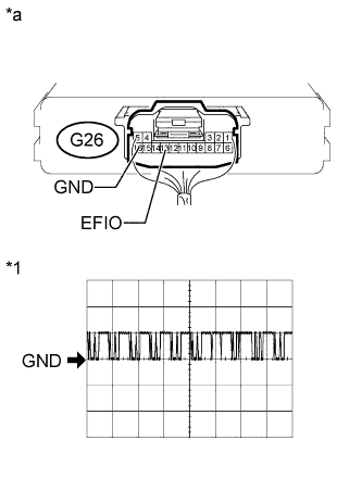
| 4.CHECK TRANSPONDER KEY ECU ASSEMBLY (TERMINAL EFIO) |
Using an oscilloscope, check the waveform.
Measurement ConditionItem
| Content
|
Tester Connection
| G26-13 (EFIO) - G26-16 (GND)
|
Tool Setting
| 10V/DIV., 100 ms./DIV.
|
Condition
| Ignition switch ON
|
- HINT:
- The waveform shown in the illustration is an example for reference only. Noise, chattering, etc. are not shown.
- OK:
- Waveform is output normally (refer to illustration).
Text in Illustration*1
| Waveform
|
*a
| Component with harness connected
(Transponder Key ECU Assembly)
|
| OK |
|
|
|
| REPLACE TRANSPONDER KEY ECU ASSEMBLY |
|
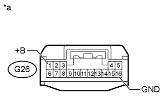
| 5.CHECK HARNESS AND CONNECTOR (TRANSPONDER KEY ECU - BATTERY AND BODY GROUND) |
Disconnect the G26 transponder key ECU assembly connector.
Measure the resistance according to the value(s) in the table below.
- Standard Resistance:
Tester Connection
| Condition
| Specified Condition
|
G26-16 (GND) - Body ground
| Always
| Below 1 Ω
|
Measure the voltage according to the value(s) in the table below.
- Standard Voltage:
Tester Connection
| Condition
| Specified Condition
|
G26-1 (+B) - Body ground
| Always
| 11 to 14 V
|
Text in Illustration*a
| Front view of wire harness connector
(to Transponder Key ECU Assembly)
|
| | REPAIR OR REPLACE HARNESS OR CONNECTOR |
|
|
Temporarily replace the ECM with a new one.
- for 1KD-FTV: HILUX_TGN26 RM000000VW202KX.html
- for 2KD-FTV: HILUX_TGN26 RM0000013Z001HX.html
- for 2TR-FE: HILUX_TGN26 RM000000VW202LX.html
- for 2TR-FBE: HILUX_TGN26 RM000000VW2024X.html
| 7.REGISTER ECU COMMUNICATION ID |
Register the ECU - ECM communication ID (Refer to the Service Bulletin).
Clear the DTCs (HILUX_TGN26 RM000000Z3I00TX.html).
Check for DTCs (HILUX_TGN26 RM000000Z3I00TX.html).
- OK:
- DTC B279A is not output.
ResultResult
| Proceed to
|
OK
| A
|
NG (w/o Blocking System)
| B
|
NG (w/ Blocking System)
| C
|
| | REPLACE TRANSPONDER KEY ECU ASSEMBLY |
|
|
| |
|
| 10.REPLACE TRANSPONDER KEY ECU ASSEMBLY |
Temporarily replace the transponder key ECU assembly with a new one (Refer to the service Bulletin).
| 11.REGISTER ECU COMMUNICATION ID |
Register the ECU - ECM communication ID (Refer to the Service Bulletin).
Clear the DTCs (HILUX_TGN26 RM000000Z3I00TX.html).
Check for the DTCs (HILUX_TGN26 RM000000Z3I00TX.html).
- OK:
- DTC B279A is not output.
| | REPLACE TELEPHONE TRANSCEIVER ASSEMBLY |
|
|
| OK |
|
|
|
| END (TRANSPONDER KEY ECU IS DEFECTIVE) |
|