DESCRIPTION
WIRING DIAGRAM
INSPECTION PROCEDURE
PERFORM ACTIVE TEST USING INTELLIGENT TESTER (ACTIVATE THE VSV FOR SWIRL CONTROL VALVE)
INSPECT VACUUM SWITCHING VALVE FOR SWIRL CONTROL VALVE (RESISTANCE)
INSPECT VACUUM SWITCHING VALVE (FOR SWIRL CONTROL VALVE) (POWER SOURCE VOLTAGE)
CHECK HARNESS AND CONNECTOR (VACUUM SWITCHING VALVE [FOR SWIRL CONTROL VALVE] - ECM)
REPLACE ECM
CHECK HARNESS AND CONNECTOR (VACUUM SWITCHING VALVE [FOR SWIRL CONTROL VALVE] - NO. 1 INTEGRATION RELAY)
INSPECT ECM POWER SOURCE CIRCUIT
REPLACE VACUUM SWITCHING VALVE (FOR SWIRL CONTROL VALVE)
REPAIR OR REPLACE HARNESS OR CONNECTOR
CONFIRM WHETHER MALFUNCTION HAS BEEN SUCCESSFULLY REPAIRED
DTC P2009 Intake Manifold Runner Control Circuit Low (Bank 1) |
DTC P2010 Intake Manifold Runner Control Circuit High (Bank 1) |
DESCRIPTION
Refer to DTC P2006 (HILUX_TGN26 RM000000YGW023X.html).P2009DTC Detection Drive Pattern
| DTC Detection Condition
| Trouble Area
|
2 seconds after engine is started, race engine for 1 second
| Open in vacuum switching valve (for swirl control valve) circuit for 0.5 seconds (2 trip detection logic).
| - Vacuum switching valve (for swirl control valve)
- Open in vacuum switching valve (for swirl control valve) circuit
- ECM
|
P2010DTC Detection Drive Pattern
| DTC Detection Condition
| Trouble Area
|
2 seconds after engine is started, race engine for 1 second
| Short in vacuum switching valve (for swirl control valve) circuit for 0.5 seconds (2 trip detection logic).
| - Vacuum switching valve (for swirl control valve)
- Short in vacuum switching valve (for swirl control valve) circuit
- ECM
|
WIRING DIAGRAM
Refer to DTC P2006 (HILUX_TGN26 RM000000YGW023X_02.html).
INSPECTION PROCEDURE
- NOTICE:
- After replacing the ECM, the new ECM needs registration (HILUX_TGN26 RM0000012XK042X.html) and initialization (HILUX_TGN26 RM000000TIN04EX.html).
- HINT:
- Read freeze frame data using the intelligent tester. Freeze frame data records the engine condition when a malfunction is detected. When troubleshooting, freeze frame data can help determine if the vehicle was moving or stationary, if the engine was warmed up or not, and other data from the time the malfunction occurred.
| 1.PERFORM ACTIVE TEST USING INTELLIGENT TESTER (ACTIVATE THE VSV FOR SWIRL CONTROL VALVE) |
Connect the intelligent tester to the DLC3.
Disconnect the vacuum hoses from the vacuum switching valve (for Swirl Control Valve).
Turn the ignition switch to ON and turn the tester on.
Enter the following menus: Powertrain / Engine and ECT / Active Test / Activate the VSV for Swirl Control Valve.
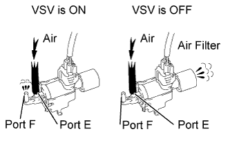
Check the VSV operation when it is operated using the intelligent tester.
- OK:
Tester Operation
| Specified Condition
|
VSV ON
| Air from port E flows out through port F
|
VSV OFF
| Air from port E flows out through air filter
|
Reconnect the vacuum hoses.
| 2.INSPECT VACUUM SWITCHING VALVE FOR SWIRL CONTROL VALVE (RESISTANCE) |
Inspect the vacuum switching valve (for swirl control valve) (HILUX_TGN26 RM00000143W01BX.html).
| 3.INSPECT VACUUM SWITCHING VALVE (FOR SWIRL CONTROL VALVE) (POWER SOURCE VOLTAGE) |
Disconnect the vacuum switching valve (for swirl control valve) connector.
Measure the voltage according to the value(s) in the table below.
- Standard Voltage:
Tester Connection
| Switch Condition
| Specified Condition
|
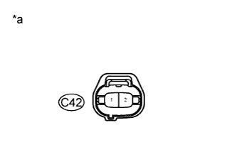
C42-2 - Body ground
| Ignition switch ON
| 11 to 14 V
|
Text in Illustration*a
| Front view of wire harness connector
(to Vacuum Switching Valve [for Swirl Control Valve])
|
| 4.CHECK HARNESS AND CONNECTOR (VACUUM SWITCHING VALVE [FOR SWIRL CONTROL VALVE] - ECM) |
Disconnect the vacuum switching valve (for swirl control valve) connector.
Disconnect the ECM connector.
Measure the resistance according to the value(s) in the table below.
- Standard Resistance:
Tester Connection
| Condition
| Specified Condition
|
C42-1 - C22-15 (SCV)
| Always
| Below 1 Ω
|
C42-1 or C22-15 (SCV) - Body ground
| Always
| 10 kΩ or higher
|
Reconnect the vacuum switching valve (for swirl control valve) connector.
Reconnect the ECM connector.
Replace the ECM (HILUX_TGN26 RM0000013Z0019X.html).
| 6.CHECK HARNESS AND CONNECTOR (VACUUM SWITCHING VALVE [FOR SWIRL CONTROL VALVE] - NO. 1 INTEGRATION RELAY) |
Remove the No. 1 integration relay from the engine room relay block and junction block assembly.
Disconnect the No. 1 integration relay connector.
Disconnect the vacuum switching valve (for swirl control valve) connector.
Measure the resistance according to the value(s) in the table below.
- Standard Resistance:
Tester Connection
| Condition
| Specified Condition
|
1J-5 - C42-2
| Always
| Below 1 Ω
|
1J-5 or C42-2 - Body ground
| Always
| 10 kΩ or higher
|
Reinstall the No. 1 integration relay.
Reconnect the No. 1 integration relay connector.
Reconnect the vacuum switching valve (for swirl control valve) connector.
| 7.INSPECT ECM POWER SOURCE CIRCUIT |
Check the ECM power source circuit (HILUX_TGN26 RM000000TI203VX.html).
| 8.REPLACE VACUUM SWITCHING VALVE (FOR SWIRL CONTROL VALVE) |
Replace the vacuum switching valve (for swirl control valve) (HILUX_TGN26 RM00000143Y01MX.html).
| 9.REPAIR OR REPLACE HARNESS OR CONNECTOR |
Repair or replace harness or connector.
| 10.CONFIRM WHETHER MALFUNCTION HAS BEEN SUCCESSFULLY REPAIRED |
Connect the intelligent tester to the DLC3.
Clear the DTCs (HILUX_TGN26 RM000000PDK0T9X.html).
Start the engine and wait for 3 seconds or more.
Enter the following menus: Powertrain / Engine and ECT / DTC.
Confirm that the DTC is not output again.