Intake Manifold (W/O Glow Plug Controller) -- Inspection |
| 1. INSPECT INTAKE MANIFOLD |
- NOTICE:
- Do not adjust the adjusting screw or 2 actuator installation bolts.

| *A | w/ EGR Cooler | *B | w/o EGR Cooler |
Disconnect the vacuum hose from the actuator.
w/ EGR Cooler:
Check the operation of the swirl control valve.

Check that the valve is fully opened under normal conditions.
Connect the vacuum pumps as shown in the illustration. First apply negative pressure to the diaphragm closer to the intake manifold. This will cause the actuator rod to move, which causes the swirl control valve to move. Then, apply negative pressure to the diaphragm on the outer side. This will cause the actuator rod to move further, which also causes the swirl control valve to move further. Check that the valve is fully closed when a negative pressure of 35 kPa (263 mmHg, 10 in.Hg) is applied.
Leave it for 1 minute and check that the vacuum pump needle does not move. If the result is not as specified, replace the intake manifold.
w/o EGR Cooler:
Check the operation of the swirl control valve.
Check that the valve is fully opened under normal conditions.
Connect a vacuum pump to the control valve. Check that the valve is fully closed when a negative pressure of 35 kPa (263 mmHg, 10 in.Hg) is applied.
Leave it for 1 minute and check that the vacuum pump needle does not move.
If the result is not as specified, replace the intake manifold.

| 2. INSPECT VACUUM SWITCHING VALVE (for Swirl Control Valve) |
Measure the resistance according to the value(s) in the table below.
- Standard Resistance:
Tester Connection Condition Specified Condition 1 - 2 20°C (68°F) 33 to 39 Ω 1 - Body ground
2 - Body ground20°C (68°F) 10 kΩ or higher
Replace Parts w/ EGR Cooler Vacuum Control Valve Set w/o EGR Cooler Intake Manifold
Check the operation according to the value(s) in the table below.
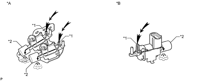
Text in Illustration *A w/ EGR Cooler *B w/o EGR Cooler *1 Port E *2 Filter 
Airflow - - Check that air flows from port E to the filter.
If the result is not as specified, replace in the table below.Replace Parts w/ EGR Cooler Vacuum Control Valve Set w/o EGR Cooler Intake Manifold Apply battery voltage across the terminals.
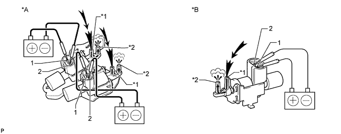
Text in Illustration *A w/ EGR Cooler *B w/o EGR Cooler *1 Port E *2 Port F Airflow - - Check that air flows from port E to port F.
If the result is not as specified, replace in the table below.Replace Parts w/ EGR Cooler Vacuum Control Valve Set w/o EGR Cooler Intake Manifold