CHECK FOR ANY OTHER DTCS OUTPUT (RECORD STORED DTC AND FREEZE FRAME DATA)
REPAIR OR REPLACE AIR INTAKE SYSTEM
CHECK TURBOCHARGER SUB-ASSEMBLY (DC MOTOR OPERATION)
PERFORM ACTIVE TEST USING INTELLIGENT TESTER (ACTIVATE THE EGR VALVE CLOSE)
CHECK ELECTRIC EGR CONTROL VALVE ASSEMBLY (CHECK VACUUM)
REMOVE DEPOSIT (ELECTRIC EGR CONTROL VALVE ASSEMBLY)
READ VALUE USING INTELLIGENT TESTER (INJECTION VOLUME)
REPLACE INJECTOR ASSEMBLIES OF ALL CYLINDERS
REGISTER INJECTOR COMPENSATION CODE AND PERFORM PILOT QUANTITY LEARNING
CONFIRM WHETHER MALFUNCTION HAS BEEN SUCCESSFULLY REPAIRED
CHECK HARNESS AND CONNECTOR (TURBO MOTOR DRIVER - TURBOCHARGER SUB-ASSEMBLY)
DTC P1251 Turbocharger / Supercharger Overboost Condition (Too High) |
DESCRIPTION
- HINT:
- Refer to DTC P0046 (HILUX_TGN26 RM000002NCM01AX.html).
| DTC Detection Drive Pattern | DTC Detection Condition | Trouble Area |
| Vehicle being driven | Boost pressure is higher than the threshold* for 0.5 seconds. (1 trip detection logic). |
|
- HINT:
- *: This value changes based on engine speed, atmospheric pressure and the engine coolant temperature (the value is generally between 177 and 250 kPa).
| DTC No. | Data List |
| P1251 |
|
- HINT:
- If DTC P1251 is stored due to the VN turbo vane being stuck closed, the following symptoms may appear:
- Vehicle surge when driving with full load
- Sudden lack of power due to power being limited
WIRING DIAGRAM
Refer to DTC P0046 (HILUX_TGN26 RM000002NCM01AX_07.html).INSPECTION PROCEDURE
- HINT:
- Read freeze frame data using the intelligent tester. Freeze frame data records the engine condition when malfunctions are detected. When troubleshooting, freeze frame data can help determine if the vehicle was moving or stationary, if the engine was warmed up or not, and other data from the time the malfunction occurred.
- NOTICE:
- After replacing the ECM, the new ECM needs registration (HILUX_TGN26 RM0000012XK042X.html) and initialization (HILUX_TGN26 RM000000TIN04EX.html).
| 1.CHECK FOR ANY OTHER DTCS OUTPUT (RECORD STORED DTC AND FREEZE FRAME DATA) |
Connect the intelligent tester to the DLC3.
Turn the ignition switch to ON and turn the tester on.
Enter the following menus: Powertrain / Engine and ECT / DTC.
Read the DTCs.
- HINT:
- Record the stored DTC and Freeze Frame Data.
- Be sure to carefully examine "MAP" and "Target Booster Pressure" in the freeze frame data.
Result Result Proceed to P1251 is output A P1251 and other DTCs are output B - HINT:
- DC motor-related DTCs: P0046 (HILUX_TGN26 RM000002NCM01AX.html), P0047 and P0048 (HILUX_TGN26 RM000002PPL039X.html).
- Nozzle vane position sensor-related DTCs: P2563, P2564, P2565, P2588 and P2589 (HILUX_TGN26 RM000002PPN02HX.html).
|
| ||||
| A | |
| 2.CHECK AIR INTAKE SYSTEM |
Check if the hoses between the air cleaner and turbocharger, and turbocharger and intake manifold are damaged or disconnected.
Result Result Proceed to Hoses or pipes are damaged or disconnected A No hoses or pipes are damaged or disconnected B - HINT:
- Be sure to check if the hoses and pipes between the air cleaner and compressor are disconnected as disconnection of a hose or pipe can cause overboost. Also, check the high pressure hoses for disconnection due to overboost.
- Check for disconnection of the exhaust pipes.
- Using your hand, check whether the pipes and hoses in the intake system are securely connected.
- Check for any modifications in the intake system made by the user.
|
| ||||
| A | |
| 3.REPAIR OR REPLACE AIR INTAKE SYSTEM |
Repair or replace the malfunctioning part in the air intake system.
| NEXT | |
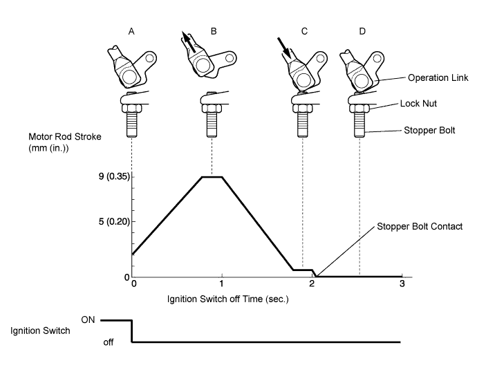
| 4.CHECK TURBOCHARGER SUB-ASSEMBLY (DC MOTOR OPERATION) |
Turn the ignition switch to ON.
Turn the ignition switch off and check the DC motor operation (check the operation link movement).
- HINT:
- When it is necessary to repeat this inspection, wait 30 seconds or more with the ignition switch off before performing the inspection.
- OK:
- When ignition switch is turned off, operation link moves as shown in A through D in illustration below.
- Operation link and motor rod move smoothly when moving from position shown in A to that shown in B, and from position shown in B to that shown in C.
|
| ||||
| OK | |
| 5.PERFORM ACTIVE TEST USING INTELLIGENT TESTER (ACTIVATE THE EGR VALVE CLOSE) |
Connect the intelligent tester to the DLC3.
Start the engine and warm it up, and make sure the A/C switch and all accessory switches are off.
Turn the ignition switch off. Wait for 30 seconds, and then restart the engine.
Turn the tester on.
Enter the following menus: Powertrain / Engine and ECT / Data List / MAF.
Read the MAF value displayed on the tester while the engine is idling.
Enter the following menus: Powertrain / Engine and ECT / Activate the EGR Valve Close.
Read the MAF value when the EGR valve is closed using the Active Test function.
- HINT:
- If idling continues for 15 minutes or more, the EGR valve target opening angle becomes 0% (EGR valve fully closed). As this makes diagnosis impossible, it becomes necessary to drive the vehicle or to restart the engine.
- Before performing the diagnosis, confirm that the EGR valve target opening angle is not 0%.
Result Active Test Result Proceed to Activate the EGR Valve Close:
Off (Open) to on (Closed)MAF value does not change A MAF value changes B - NOTICE:
- As the values shown below may differ due to factors such as differences in measuring environments and changes in vehicle condition due to aging, do not use these values to determine whether the vehicle is malfunctioning or not.
- HINT:
- The problem may be a temporary one, due to the entry of deposits or foreign matter. Check that there are no deposits or foreign matter in the electric vacuum regulating valve assembly or mass air flow meter.
- Reference:
EGR Valve Condition (Opening) Measuring Condition MAF (Reference) Open (55%) - Atmosphere pressure: 101 kPa
- Intake air temperature: 30°C (86°F)
- Engine coolant temperature: 88°C (190°F)
3.0 to 9.0 gm/s Close (0%) 15 to 22 gm/s - Atmosphere pressure: 101 kPa
|
| ||||
| A | |
| 6.CHECK ELECTRIC EGR CONTROL VALVE ASSEMBLY (CHECK VACUUM) |
Disconnect the vacuum hose from the electric EGR control valve assembly.
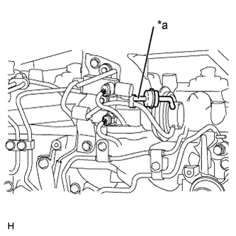 |
Start the engine.
Check if there is suction from the vacuum hose during idling.
- HINT:
- If idling continues for 15 minutes or more, the EGR valve target opening angle becomes 0% (EGR valve fully closed). As this makes diagnosis impossible, it becomes necessary to drive the vehicle or to restart the engine.
- OK:
- Suction exists.
Text in Illustration *a Vacuum Hose
|
| ||||
| OK | |
| 7.REMOVE DEPOSIT (ELECTRIC EGR CONTROL VALVE ASSEMBLY) |
Remove the electric EGR control valve assembly (HILUX_TGN26 RM000002RK901IX.html).
Visually check the electric EGR control valve assembly for deposits. If there are deposits, clean the electric EGR control valve assembly.
- HINT:
- If the EGR valve is stuck closed, the intake air amount increases and engine vibration may worsen.
- If the EGR valve does not operate due to clogging or disconnection of the vacuum hose, repair the hose.
- If the EGR valve does not close properly or is stuck open, EGR becomes excessive and combustion becomes unstable. Also, there may be a lack of power.
Reinstall the electric EGR control valve assembly (HILUX_TGN26 RM000002RK601IX.html).
|
| ||||
| 8.REPAIR OR REPLACE VACUUM HOSE |
Repair or replace of the EGR valve system vacuum hose.
|
| ||||
| 9.READ VALUE USING INTELLIGENT TESTER (INJECTION VOLUME) |
Connect the intelligent tester to the DLC3.
Start the engine and warm it up until the engine coolant temperature reaches 70°C (158°F) or higher.
Allow the engine to idle for 1 minute or more.
- HINT:
- The A/C switch and all accessory switches should be off with a fully warm engine.
Turn the tester on.
Enter the following menus: Powertrain / Engine and ECT / Data List / Injection Volume.
Read the values during engine idling.
Result Result Proceed to Injection Volume is less than 4 mm3/st A Except above B - HINT:
- If the injector assembly is malfunctioning, the compensatory injection volume remains at 5.0 mm3/st.
- If there is a disconnection, the feedback value will increase and +5.0 mm3/st will be indicated, because it will become impossible for the injector to inject.
|
| ||||
| A | |
| 10.REPLACE INJECTOR ASSEMBLIES OF ALL CYLINDERS |
Replace the injector assemblies (HILUX_TGN26 RM000002SY101RX.html).
| NEXT | |
| 11.BLEED AIR FROM FUEL SYSTEM |
Bleed the air from the fuel system (HILUX_TGN26 RM000002SY8025X_01_0002.html).
| NEXT | |
| 12.REGISTER INJECTOR COMPENSATION CODE AND PERFORM PILOT QUANTITY LEARNING |
Register the injector compensation code (HILUX_TGN26 RM0000012XK042X_02_0003.html).
Perform the injector pilot quantity learning (HILUX_TGN26 RM0000012XK042X_02_0009.html).
| NEXT | |
| 13.CONFIRM WHETHER MALFUNCTION HAS BEEN SUCCESSFULLY REPAIRED |
Connect the intelligent tester to the DLC3.
Turn the ignition switch to ON and turn the tester on.
Clear the DTCs (HILUX_TGN26 RM000000PDK0T9X.html).
Turn the ignition switch off.
Remove the EFI fuse from the engine room relay block and junction block assembly for more than 1 minute.
Turn the ignition switch to ON and wait for 10 seconds or more.
Start the engine.
Drive the vehicle with a city driving pattern at least 10 minutes.
Confirm the value of Engine Speed from the Freeze Frame Data recorded previously, and then drive the vehicle according to the Engine Speed value.
- HINT:
- Take a snapshot of MAP and Target Boost Pressure in the Data List with the intelligent tester while driving the vehicle.
Enter the following menus: Powertrain / Engine and ECT / DTC.
Read the DTCs.
Result Result Proceed to P1251 is not output and the amount by which MAP exceeds Target Boost Pressure is 20 kPa or less A Except above B* - HINT:
- *: Return to "Check Air Intake System" and inspect areas that have not been inspected yet.
|
| ||||
| A | ||
| ||
| 14.CHECK HARNESS AND CONNECTOR (TURBO MOTOR DRIVER - TURBOCHARGER SUB-ASSEMBLY) |
Disconnect the DC motor connector.
Disconnect the nozzle vane position sensor connector.
Disconnect the turbo motor driver connector.
Measure the resistance according to the value(s) in the table below.
- Standard Resistance:
Tester Connection Condition Specified Condition C41-2 (M+) - C39-12 (M+) Always Below 1 Ω C41-1 (M-) - C39-5 (M-) Always Below 1 Ω C40-1 (VTA1) - C39-9 (VTA1) Always Below 1 Ω C40-2 (VNE2) - C39-8 (VNE2) Always Below 1 Ω C40-3 (VNVC) - C39-1 (VNVC) Always Below 1 Ω C40-4 (VTA2) - C39-10 (VTA2) Always Below 1 Ω C40-5 (E2S) - C39-11 (E2S) Always Below 1 Ω C40-6 (VCS) - C39-6 (VCS) Always Below 1 Ω C41-2 (M+) or C39-12 (M+) - Body ground Always 10 kΩ or higher C41-1 (M-) or C39-5 (M-) - Body ground Always 10 kΩ or higher C40-1 (VTA1) or C39-9 (VTA1) - Body ground Always 10 kΩ or higher C40-2 (VNE2) or C39-8 (VNE2) - Body ground Always 10 kΩ or higher C40-3 (VNVC) or C39-1 (VNVC) - Body ground Always 10 kΩ or higher C40-4 (VTA2) or C39-10 (VTA2) - Body ground Always 10 kΩ or higher C40-5 (E2S) or C39-11 (E2S) - Body ground Always 10 kΩ or higher C40-6 (VCS) or C39-6 (VCS) - Body ground Always 10 kΩ or higher
Reconnect the DC motor connector.
Reconnect the nozzle vane position sensor connector.
Reconnect the turbo motor driver connector.
|
| ||||
| OK | ||
| ||