CHECK FOR ANY OTHER DTCS OUTPUT (IN ADDITION TO DTC P2563, P2564, P2565, P2588 AND/OR P2589)
CHECK HARNESS AND CONNECTOR (NOZZLE VANE POSITION SENSOR - TURBO MOTOR DRIVER)
CHECK TURBO MOTOR DRIVER (SENSOR POWER SOURCE)
INSPECT TURBO MOTOR DRIVER (VTA1, VTA2 VOLTAGE)
CHECK WHETHER DTC OUTPUT RECURS (DTC P2563, P2564, P2565, P2588 AND/OR P2589)
REPLACE TURBOCHARGER SUB-ASSEMBLY (NOZZLE VANE POSITION SENSOR)
REPAIR OR REPLACE HARNESS OR CONNECTOR
CONFIRM WHETHER MALFUNCTION HAS BEEN SUCCESSFULLY REPAIRED
DTC P2563 Turbocharger/Supercharger Boost Control Position Sensor "A" Circuit Range/Performance |
DTC P2564 Turbocharger/Supercharger Boost Control Position Sensor "A" Circuit Low |
DTC P2565 Turbocharger/Supercharger Boost Control Position Sensor "A" Circuit High |
DTC P2588 Turbocharger/Supercharger Boost Control Position Sensor "B" Circuit Low |
DTC P2589 Turbocharger/Supercharger Boost Control Position Sensor "B" Circuit High |
DESCRIPTION
Variable nozzle vane type turbocharger consists primarily of a compressor wheel, turbine wheel, nozzle vane, unison ring, DC motor and nozzle vane position sensor.The nozzle vane position sensor consists of a Hall IC and a magnetic yoke that rotates in unison with the movement of the linkage that actuates the nozzle vane. The nozzle vane position sensor converts the changes in the magnetic flux that are caused by the rotation of the DC motor (hence, the rotation of the magnetic yoke) into electric signals, and outputs them to the turbo motor driver. The turbo motor driver determines the actual nozzle vane position from the electric signals in order to calculate the target nozzle vane position.

| DTC Detection Drive Pattern | DTC Detection Condition | Trouble Area |
| Ignition switch to ON for 1 seconds | Difference between VTA1 and VTA2 voltage 0.8 V or more for 0.5 seconds or more (1 trip detection logic) | Nozzle vane position sensor (Turbocharger sub-assembly) |
| DTC Detection Drive Pattern | DTC Detection Condition | Trouble Area |
| Ignition switch to ON for 1 seconds | VTA1 voltage 0.5 V or less for 0.5 seconds or more (1 trip detection logic) |
|
| DTC Detection Drive Pattern | DTC Detection Condition | Trouble Area |
| Ignition switch to ON for 1 seconds | VTA1 voltage 4.5 V or more for 0.5 seconds or more (1 trip detection logic) |
|
| DTC Detection Drive Pattern | DTC Detection Condition | Trouble Area |
| Ignition switch to ON for 1 seconds | VTA2 voltage 0.5 V or less for 0.5 seconds or more (1 trip detection logic) |
|
| DTC Detection Drive Pattern | DTC Detection Condition | Trouble Area |
| Ignition switch to ON for 1 seconds | VTA2 voltage 4.5 V or more for 0.5 seconds or more (1 trip detection logic) |
|
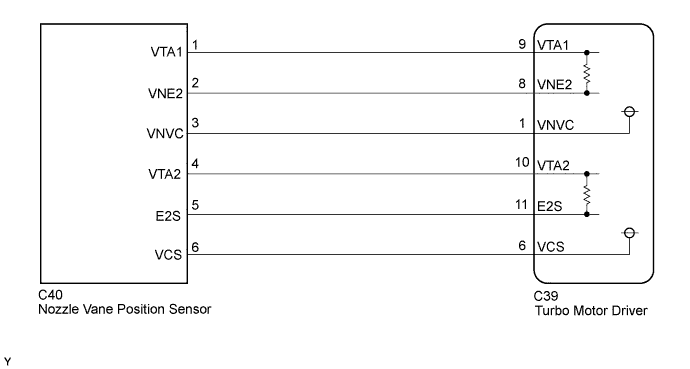
WIRING DIAGRAM
INSPECTION PROCEDURE
- HINT:
- Read freeze frame data using the intelligent tester. Freeze frame data records the engine condition when malfunctions are detected. When troubleshooting, freeze frame data can help determine if the vehicle was moving or stationary, if the engine was warmed up or not, and other data from the time the malfunction occurred.
| 1.CHECK FOR ANY OTHER DTCS OUTPUT (IN ADDITION TO DTC P2563, P2564, P2565, P2588 AND/OR P2589) |
Connect the intelligent tester to the DLC3.
Turn the ignition switch to ON and turn the tester on.
Enter the following menus: Powertrain / Engine and ECT / DTC.
Read the DTCs.
Result Result Proceed to P2563, P2564, P2565, P2588 and/or P2589 is output A P2563, P2564, P2565, P2588 and/or P2589 and other DTCs are output B
|
| ||||
| A | |
| 2.CHECK HARNESS AND CONNECTOR (NOZZLE VANE POSITION SENSOR - TURBO MOTOR DRIVER) |
Disconnect the nozzle vane position sensor connector.
Disconnect the turbo motor driver connector.
Measure the resistance according to the value(s) in the table below.
- Standard Resistance:
Tester Connection Condition Specified Condition C40-1 (VTA1) - C39-9 (VTA1) Always Below 1 Ω C40-2 (VNE2) - C39-8 (VNE2) Always Below 1 Ω C40-3 (VNVC) - C39-1 (VNVC) Always Below 1 Ω C40-4 (VTA2) - C39-10 (VTA2) Always Below 1 Ω C40-5 (E2S) - C39-11 (E2S) Always Below 1 Ω C40-6 (VCS) - C39-6 (VCS) Always Below 1 Ω C40-1 (VTA1) or C39-9 (VTA1) - Body ground Always 10 kΩ or higher C40-2 (VNE2) or C39-8 (VNE2) - Body ground Always 10 kΩ or higher C40-3 (VNVC) or C39-1 (VNVC) - Body ground Always 10 kΩ or higher C40-4 (VTA2) or C39-10 (VTA2) - Body ground Always 10 kΩ or higher C40-5 (E2S) or C39-11 (E2S) - Body ground Always 10 kΩ or higher C40-6 (VCS) or C39-6 (VCS) - Body ground Always 10 kΩ or higher
Reconnect the turbo motor driver connector.
Reconnect the nozzle vane position sensor connector.
|
| ||||
| OK | |
| 3.CHECK TURBO MOTOR DRIVER (SENSOR POWER SOURCE) |
Disconnect the nozzle vane position sensor connector.
 |
Turn the ignition switch to ON.
Measure the voltage according to the value(s) in the table below.
- Standard Voltage:
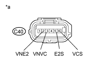
Tester Connection Switch Condition Specified Condition C40-3 (VNVC) - C40-2 (VNE2) Ignition switch ON 4.5 to 5.5 V C40-6 (VCS) - C40-5 (E2S) Ignition switch ON 4.5 to 5.5 V
Text in Illustration *a Front view of with harness connector
(to Nozzle Vane Position Sensor)
Reconnect the nozzle vane position sensor connector.
|
| ||||
| OK | |
| 4.INSPECT TURBO MOTOR DRIVER (VTA1, VTA2 VOLTAGE) |
Turn the ignition switch to ON.
 |
Measure the voltage according to the value(s) in the table below.
- Standard Voltage:
Tester Connection Switch Condition Specified Condition C39-9 (VTA1) - C39-8 (VNE2) Ignition switch ON 0.5 to 4.5 V C39-10 (VTA2) - C39-11 (E2S) Ignition switch ON 0.5 to 4.5 V
Text in Illustration *a Component with harness connected
(Turbo Motor Driver)
Check the difference between the voltage values.
- Result:
- Voltage difference between VTA1 and VTA2 is within 0.8 V
|
| ||||
| OK | |
| 5.REPLACE TURBO MOTOR DRIVER |
Replace turbo motor driver (HILUX_TGN26 RM000004QB2006X.html).
| NEXT | |
| 6.CHECK WHETHER DTC OUTPUT RECURS (DTC P2563, P2564, P2565, P2588 AND/OR P2589) |
Connect the intelligent tester to the DLC3.
Turn the ignition switch to ON and turn the tester on.
Clear the DTCs (HILUX_TGN26 RM000000PDK0T9X.html).
Turn the ignition switch off.
Remove the EFI fuse from the engine room relay block and junction block assembly for more than 1 minute.
Turn the ignition switch to ON and wait for 10 seconds or more.
Start the engine.
Drive the vehicle with a city driving pattern at least 10 minutes.
Enter the following menus: Powertrain / Engine and ECT / DTC.
Read the DTCs.
Result Result Proceed to P2563, P2564, P2565, P2588 and/or P2589 output again A No DTC is output B
|
| ||||
| A | |
| 7.REPLACE TURBOCHARGER SUB-ASSEMBLY (NOZZLE VANE POSITION SENSOR) |
Replace turbocharger sub-assembly (HILUX_TGN26 RM00000143U00WX.html).
|
| ||||
| 8.REPAIR OR REPLACE HARNESS OR CONNECTOR |
Repair or replace the harness or connector.
| NEXT | |
| 9.CONFIRM WHETHER MALFUNCTION HAS BEEN SUCCESSFULLY REPAIRED |
Connect the intelligent tester to the DLC3.
Turn the ignition switch to ON and turn the tester on.
Clear the DTCs (HILUX_TGN26 RM000000PDK0T9X.html).
Turn the ignition switch off.
Remove the EFI fuse from the engine room relay block and junction block assembly for more than 1 minute.
Turn the ignition switch to ON and wait for 10 seconds or more.
Start the engine.
Drive the vehicle with a city driving pattern at least 10 minutes.
Enter the following menus: Powertrain / Engine and ECT / DTC.
Confirm that the DTC is not output again.
| NEXT | ||
| ||