CHECK COMMUNICATION BETWEEN INTELLIGENT TESTER AND ECM
CHECK MIL (ACCELERATOR PEDAL POSITION SENSOR)
CHECK MIL (THROTTLE POSITION SENSOR)
CHECK MIL (FUEL PRESSURE SENSOR)
CHECK MIL (ELECTRIC EGR CONTROL VALVE ASSEMBLY)
CHECK MIL (DIFFERENTIAL PRESSURE SENSOR ASSEMBLY)
CHECK MIL (MANIFOLD ABSOLUTE PRESSURE SENSOR)
CHECK MIL (NOZZLE VANE POSITION SENSOR)
ECD SYSTEM (for DPF) - VC Output Circuit |
DESCRIPTION
The ECM constantly generates 5 V of power from the battery voltage supplied to the +B (BATT) terminal to operate the microprocessor. The ECM also provides this power to the sensors through the VC output circuit.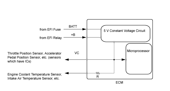
When the VC circuit is short-circuited, the microprocessor in the ECM and sensors that are supplied with power through the VC circuit are inactivated because the power is not supplied from the VC circuit. Under this condition, the system does not start up and the MIL does not illuminate even if the system malfunctions.
- HINT:
- Under normal conditions, the MIL is illuminated for several seconds when the ignition switch is first turned to ON. The MIL goes off when the engine is started.
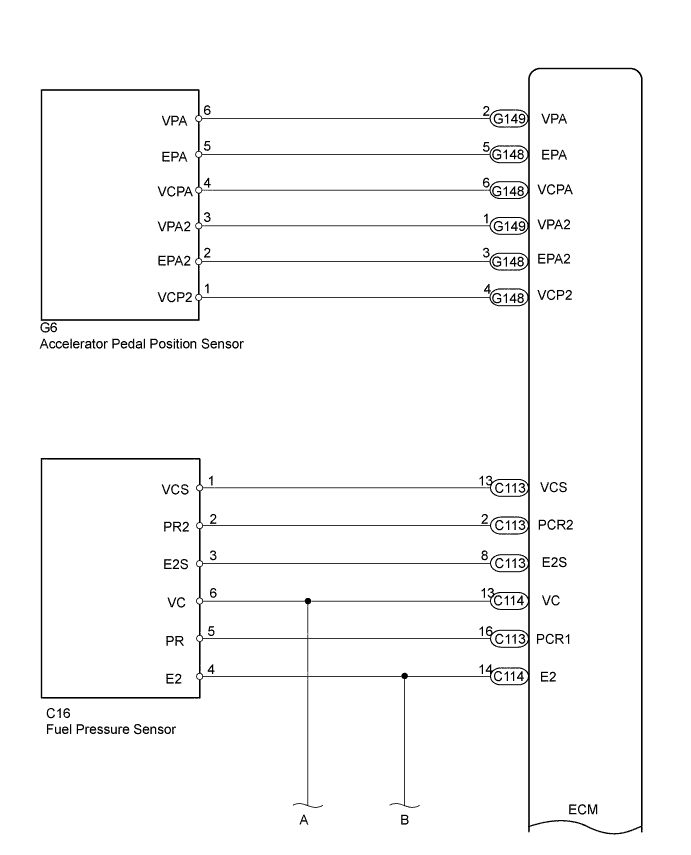
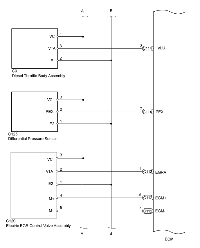
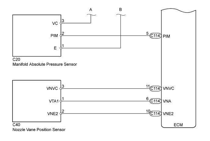
WIRING DIAGRAM
INSPECTION PROCEDURE
- NOTICE:
- Inspect the fuses of circuits related to this system before performing the following inspection procedure.
- After replacing the ECM, the new ECM needs registration (HILUX_TGN26 RM0000012XK058X.html) and initialization (HILUX_TGN26 RM000000TIN056X.html).
- After replacing the fuel supply pump assembly, the ECM needs initialization (HILUX_TGN26 RM000000TIN056X.html).
- After replacing an injector assembly, the ECM needs registration (HILUX_TGN26 RM0000012XK058X.html).
| 1.CHECK MIL |
Check that the Malfunction Indicator Lamp (MIL) lights up when turning the ignition switch to ON.
Result Result Proceed to MIL illuminates A MIL does not illuminate B
|
| ||||
| B | |
| 2.CHECK COMMUNICATION BETWEEN INTELLIGENT TESTER AND ECM |
Connect the intelligent tester to the DLC3.
Turn the ignition switch to ON and tester on.
Check the communication between the tester and ECM.
Result Result Proceed to Communication is possible A Communication is not possible B
|
| ||||
| B | |
| 3.CHECK MIL (ACCELERATOR PEDAL POSITION SENSOR) |
Disconnect the accelerator pedal position sensor connector.
Turn the ignition switch to ON.
Check the MIL.
Result Result Proceed to MIL illuminates A MIL does not illuminate B
Reconnect the accelerator pedal position sensor connector.
|
| ||||
| B | |
| 4.CHECK MIL (THROTTLE POSITION SENSOR) |
Disconnect the throttle position sensor connector.
Turn the ignition switch to ON.
Check the MIL.
Result Result Proceed to MIL illuminates A MIL does not illuminate B
Reconnect the throttle position sensor connector.
|
| ||||
| B | |
| 5.CHECK MIL (FUEL PRESSURE SENSOR) |
Disconnect the fuel pressure sensor connector.
Turn the ignition switch to ON.
Check the MIL.
Result Result Proceed to MIL illuminates A MIL does not illuminate B
Reconnect the fuel pressure sensor connector.
|
| ||||
| B | |
| 6.CHECK MIL (ELECTRIC EGR CONTROL VALVE ASSEMBLY) |
Disconnect the electric EGR control valve assembly connector.
Turn the ignition switch to ON.
Check the MIL.
Result Result Proceed to MIL illuminates A MIL does not illuminate B
Reconnect the electric EGR control valve assembly connector.
|
| ||||
| B | |
| 7.CHECK MIL (DIFFERENTIAL PRESSURE SENSOR ASSEMBLY) |
Disconnect the differential pressure sensor assembly connector.
Turn the ignition switch to ON.
Check the MIL.
Result Result Proceed to MIL illuminates A MIL does not illuminate B
Reconnect the differential pressure sensor assembly connector.
|
| ||||
| B | |
| 8.CHECK MIL (MANIFOLD ABSOLUTE PRESSURE SENSOR) |
Disconnect the manifold absolute pressure sensor connector.
Turn the ignition switch to ON.
Check the MIL.
Result Result Proceed to MIL illuminates A MIL does not illuminate B
Reconnect the manifold absolute pressure sensor connector.
|
| ||||
| B | |
| 9.CHECK MIL (NOZZLE VANE POSITION SENSOR) |
Disconnect the nozzle vane position sensor connector.
Turn the ignition switch to ON.
Check the MIL.
Result Result Proceed to MIL illuminates A MIL does not illuminate B
Reconnect the nozzle vane position sensor connector.
|
| ||||
| B | |
| 10.CHECK HARNESS AND CONNECTOR |
Disconnect the accelerator pedal position sensor connector.
Disconnect the throttle position sensor connector.
Disconnect the fuel pressure sensor connector.
Disconnect the electric EGR control valve assembly connector.
Disconnect the differential pressure sensor assembly connector.
Disconnect the nozzle vane position sensor connector.
Disconnect the manifold absolute pressure sensor connector.
Disconnect the ECM connectors.
Measure the resistance according to the value(s) in the table below.
- Standard Resistance:
Tester Connection Condition Specified Condition G148-6 (VCPA) - Body ground Always 10 kΩ or higher G148-4 (VCP2) - Body ground Always 10 kΩ or higher C114-13 (VC) - Body ground Always 10 kΩ or higher C113-13 (VCS) - Body ground Always 10 kΩ or higher C114-11 (VNVC) - Body ground Always 10 kΩ or higher
Reconnect the accelerator pedal position sensor connector.
Reconnect the throttle position sensor connector.
Reconnect the fuel pressure sensor connector.
Reconnect the electric EGR control valve assembly connector.
Reconnect the differential pressure sensor assembly connector.
Reconnect the nozzle vane position sensor connector.
Reconnect the manifold absolute pressure sensor connector.
Reconnect the ECM connectors.
|
| ||||
| OK | ||
| ||