Generator -- Installation |
| 1. INSTALL GENERATOR ASSEMBLY |
Install the generator with the 2 bolts.
- Torque:
- 43 N*m{438 kgf*cm, 32 ft.*lbf}
Install the generator wire with the bolt and nut.
- Torque:
- for nut:
- 9.8 N*m{100 kgf*cm, 87 in.*lbf}
- for bolt:
- 13 N*m{133 kgf*cm, 10 ft.*lbf}
Attach the terminal cap.
Connect the generator connector.
| 2. INSTALL FAN AND GENERATOR V BELT |
Install the fan and generator V belt to all the pulleys except the V-ribbed belt tensioner pulley.
Text in Illustration *A w/ Air Conditioning System *B w/o Air Conditioning System *1 Generator *2 Idler Pulley *3 Vane Pump *4 Fan Pulley *5 Tensioner Pulley *6 Crankshaft Pulley *7 No. 1 Idler Pulley *8 Cooler Compressor
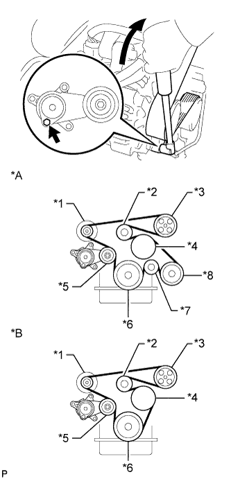 |
Use the hexagon-shaped part indicated by the arrow in the illustration to move the tensioner pulley downward, and then install the fan and generator V belt to the tensioner pulley.
- NOTICE:
- The backside of the fan and generator V belt should face the tensioner pulley.
- Check that the fan and generator V belt is properly installed to each pulley.
| 3. INSPECT FAN AND GENERATOR V BELT |
Check the belt for wear, cracks or other signs of damage.
If any of the following defects is found, replace the fan and generator V belt.- The belt is cracked.
- The belt is worn out to the extent that the cords are exposed.
- The belt has chunks missing from the ribs.
- The belt is cracked.
 |
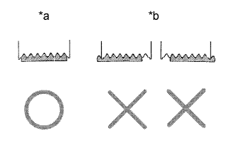
Check that the belt fits properly in the ribbed grooves.
Text in Illustration *a CORRECT *b INCORRECT - HINT:
- Check with your hand to confirm that the belt has not slipped out of the grooves on the bottom of the pulley. If it has slipped out, replace the V belt. Install a new V belt correctly.
 |
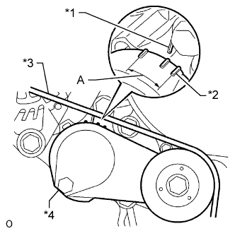
Check that the tensioner indicator mark is within range A shown in the illustration.
If the mark is not within range A, replace the fan and generator V belt.Text in Illustration *1 Bracket Side Indicator *2 Arm Side Indicator *3 Fan and Generator V Belt *4 Tensioner - HINT:
- If a new belt has been installed, check that the tensioner indicator mark is within range A.
 |
| 4. INSTALL INTAKE AIR CONNECTOR AND AIR CLEANER ASSEMBLY |
Install the air cleaner and intake air connector assembly with the 4 bolts, and tighten the hose clamp.
- Torque:
- for air cleaner:
- 14 N*m{143 kgf*cm, 10 ft.*lbf}
- for intake air connector:
- 8.0 N*m{82 kgf*cm, 71 in.*lbf}
- for hose clamp:
- 5.0 N*m{51 kgf*cm, 44 in.*lbf}
Connect the mass air flow meter connector and attach the wire harness clamps.
Connect the No. 2 PCV hose.
Connect the vacuum hose.
| 5. CONNECT CABLE TO NEGATIVE BATTERY TERMINAL |
- NOTICE:
- When disconnecting the cable, some systems need to be initialized after the cable is reconnected (HILUX_TGN26 RM000004QR3008X.html).