Automatic Transmission Assembly -- Installation |
| 1. INSTALL TRANSMISSION CONTROL CABLE BRACKET |
Install the control cable bracket with the 2 bolts.
- Torque:
- 28 N*m{286 kgf*cm, 21 ft.*lbf}
| 2. INSPECT TORQUE CONVERTER ASSEMBLY |
| 3. INSTALL TORQUE CONVERTER ASSEMBLY |
Engage the spline of the input shaft turbine runner.
 |
Engage the spline of the stator shaft and the stator while turning the torque converter assembly.
- HINT:
- If the stator shaft spline are difficult to engage with the stator splines, move the torque converter back approximately 10 mm (0.787 in.) and engage the splines while rotating the torque converter.
 |
Turn the torque converter assembly to insert the key of the oil pump drive gear into the groove of the torque converter assembly.
 |
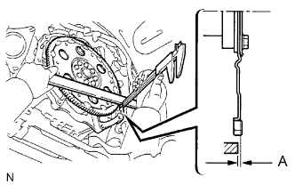
Clean the torque converter set bolt holes.
Using a vernier caliper and straightedge, measure dimension A between the transaxle contact surface of the engine and the torque converter contact surface of the drive plate.
- NOTICE:
- Make sure to deduct the thickness of the straightedge.
 |
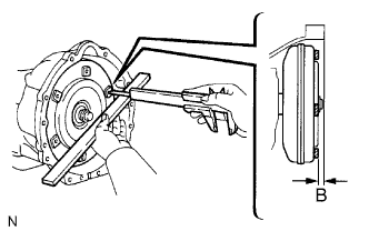
Using a vernier caliper and straightedge, measure dimension B shown in the illustration and check that dimension B is more than dimension A, which was measured in the previous step.
- Standard:
- B = A + 1.00 mm (0.0394 in.) or more
- NOTICE:
- Make sure to deduct the thickness of the straightedge.
- If the transaxle is installed to the engine with the torque converter not sufficiently inserted, the torque converter may be damaged.
 |
| 4. INSTALL AUTOMATIC TRANSMISSION ASSEMBLY |
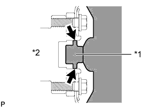
Apply clutch spline grease to the surface of the crankshaft that contacts the torque converter centerpiece.
Text in Illustration *1 Torque Converter Centerpiece *2 Crankshaft - Clutch spline grease::
- Toyota Genuine Clutch Spline Grease or equivalent
- Maximum grease amount:
- Approximately 1 g (0.0353 oz.)
 |
While keeping the engine and automatic transmission assembly horizontal, align the knock pins with the holes in the automatic transmission assembly and Install the 5 bolts.
- Torque:
- 71 N*m{720 kgf*cm, 53 ft.*lbf}
- NOTICE:
- Confirm that the 2 knock pins are installed to the transaxle contact surface of the engine cylinder block before installing the automatic transmission assembly.
- Do not forcibly pry on the automatic transmission assembly
- Check that the torque converter rotates.
Hold the crankshaft pulley bolt with a wrench and install the 6 drive plate and torque converter setting bolts.
- Torque:
- 48 N*m{489 kgf*cm, 35 ft.*lbf}
- NOTICE:
- First install the black colored bolt and then the remaining 5 silver colored bolts.
| 5. INSTALL STIFFENER PLATE |
Install the No. 2 end plate.
Install the No. 4 cylinder block insulator.
Install the stiffener plate LH to the engine and transmission with the 4 bolts.
- Torque:
- 71 N*m{720 kgf*cm, 53 ft.*lbf}
Install the stiffener plate RH (with clamp tube) to the engine and transmission with the 4 bolts.
- Torque:
- 71 N*m{720 kgf*cm, 53 ft.*lbf}
| 6. INSTALL WIRE HARNESS CLAMP BRACKET |
Install the wire harness clamp bracket with the bolt.
- Torque:
- 13 N*m{128 kgf*cm, 9 ft.*lbf}
| 7. CONNECT ENGINE WIRE |
Connect the connectors.
Connect the temperature sensor connector.
Connect the park/neutral position switch connector.
Connect the 3 speed sensor connectors.
Connect the transmission wire connector.
| 8. INSTALL REAR NO. 1 ENGINE MOUNTING INSULATOR |
Install the engine mounting insulator to the transmission with the 4 bolts.
- Torque:
- 47 N*m{479 kgf*cm, 35 ft.*lbf}
| 9. INSTALL NO. 3 FRAME CROSSMEMBER SUB-ASSEMBLY |
Install the 4 set bolts of the engine mounting insulator.
- Torque:
- 17 N*m{173 kgf*cm, 13 ft.*lbf}
Install the frame crossmember with the 4 bolts and 4 nuts.
- Torque:
- 50 N*m{510 kgf*cm, 37 ft.*lbf}
| 10. INSTALL STARTER ASSEMBLY |
| 11. CONNECT GROUND CABLE |
Connect the earth wire with the nut.
- Torque:
- 5.5 N*m{56 kgf*cm, 49 in.*lbf}
| 12. CONNECT TRANSMISSION CONTROL SHIFT CABLE ASSEMBLY |
Connect the control cable with a new clip.
Connect the control cable with the nut.
- Torque:
- 14 N*m{143 kgf*cm, 10 ft.*lbf}
| 13. INSTALL OIL COOLER TUBE |
 |
Loosely install the tip of the oil cooler tube inlet to the automatic transmission by hand.
Loosely install the tip of the oil cooler tube outlet to the automatic transmission by hand.
Install the 3 clamps with the 3 bolts.
- Torque:
- for Bolt A and B:
- 5.0 N*m{51 kgf*cm, 44 in.*lbf}
- for Bolt C:
- 12 N*m{122 kgf*cm, 9 ft.*lbf}
Using a union nut wrench, tighten the inlet and outlet tubes.
- Torque:
- 34 N*m{350 kgf*cm, 25 ft.*lbf}
- NOTICE:
- Use the formula to calculate special torque values for situations where a union nut wrench is combined with a torque wrench (HILUX_TGN26 RM000004QR1006X.html).
| 14. INSTALL TRANSMISSION OIL FILLER TUBE SUB-ASSEMBLY |
Coat a new O-ring with ATF, and install it to the oil filler tube.
Install the oil filler tube with the 2 bolts.
- Torque:
- 12 N*m{122 kgf*cm, 9 ft.*lbf}
Install the oil dipstick.
| 15. INSTALL PROPELLER SHAFT ASSEMBLY |
| 16. INSTALL FRONT PROPELLER SHAFT ASSEMBLY |
| 17. INSTALL FRONT EXHAUST PIPE ASSEMBLY |
Using a vernier caliper, measure the free length of the compression spring.
- Minimum length:
- 40 mm (1.57 in.)
 |
Install the front exhaust pipe to the exhaust pipe support.
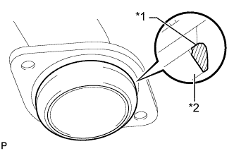
Install a new gasket to the turbine outlet elbow.
Text in Illustration *1 Gasket *2 Turbine Outlet Elbow - NOTICE:
- Be careful with the installation direction of the gasket.
- Do not reuse the gasket.
- To ensure a proper seal, do not use the front exhaust pipe to force the gasket onto the turbine outlet elbow.
- HINT:
- Using a plastic-faced hammer, uniformly strike the gasket so that the gasket and outlet pipe are properly fit.
 |
Install the front exhaust pipe and 2 compression springs with the 2 bolts. Alternately tighten the bolts in several passes.
- Torque:
- 43 N*m{438 kgf*cm, 32 ft.*lbf}
| 18. INSTALL TRANSFER HIGH AND LOW SHIFT LEVER ASSEMBLY |
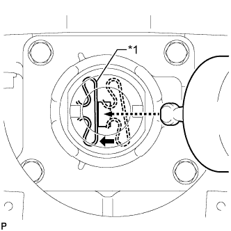
While pushing the select return spring to the left with the end of the transfer high and low shift lever, insert the end of the shift lever into the shift fork.
Text in Illustration *1 Select Return Spring
 |
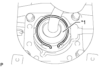
While holding down the shift lever cap, install the snap ring to install the transfer high and low shift lever.
Text in Illustration *1 Shift Lever Cap
 |
Return the transfer front drive shift boot to its original position.
| 19. INSTALL SHIFT LEVER BOOT ASSEMBLY |
Install the shift lever boot with the 4 screws.
| 20. ADJUST SHIFT LEVER POSITION |
 |
Move the shift lever to N.
Remove the nut and disconnect the control cable.
Turn the control shaft lever clockwise until it stops, and then turn it counterclockwise 2 notches to set it to the N position.
 |
While holding the control shaft lever slightly toward the R position side, connect the cable with the nut.
- Torque:
- 16 N*m{163 kgf*cm, 12 ft.*lbf}
| 21. ADD AUTOMATIC TRANSMISSION FLUID |
- Fluid type:
- Toyota Genuine ATF TYPE T-IV
| 22. CONNECT CABLE TO NEGATIVE BATTERY TERMINAL |
- NOTICE:
- When disconnecting the cable, some systems need to be initialized after the cable is reconnected (HILUX_TGN26 RM000004QR300CX.html).
| 23. INSPECT SHIFT LEVER POSITION |
When moving the shift lever from P to R with the ignition switch ON and the brake pedal depressed, make sure that the shift lever moves smoothly and correctly into position.
Start the engine and make sure that the vehicle moves forward after moving the shift lever from N to D, and moves rearward after shifting to the R.
If the results are not as specified, inspect the park/neutral position switch and check the shift lever.
| 24. CHECK FOR EXHAUST GAS LEAKS |
| 25. CHECK AUTOMATIC TRANSMISSION FLUID |
- HINT:
- Drive the vehicle so that the engine and transmission are at normal operating temperature.
- ATF temperature:
- 70 to 80° C (158 to 176° F)
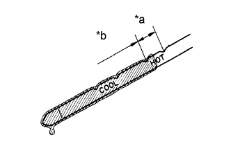
Park the vehicle on a level surface and set the parking brake.
Text in Illustration *a OK *b Add
 |
With the engine idling and the brake pedal depressed, move the shift lever to all positions from P to L. Then return it to P.
Pull out the dipstick and wipe it clean.
Push it back fully into the pipe.
Pull it out and check that the fluid level is in the HOT range.
If there are leaks, it is necessary to repair or replace O-rings, FIPG, oil seals, plugs or other parts.
| 26. INSTALL NO. 2 ENGINE UNDER COVER |
- Torque:
- 28 N*m{286 kgf*cm, 21 ft.*lbf}
| 27. INSTALL NO. 1 ENGINE UNDER COVER |
- Torque:
- 28 N*m{286 kgf*cm, 21 ft.*lbf}