Dtc P0617 Starter Relay Circuit High
DESCRIPTION
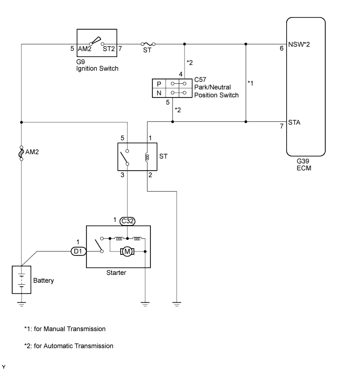
WIRING DIAGRAM
INSPECTION PROCEDURE
READ VALUE USING INTELLIGENT TESTER (STARTER SIGNAL)
INSPECT PARK/NEUTRAL POSITION SWITCH ASSEMBLY
INSPECT IGNITION SWITCH
CHECK HARNESS AND CONNECTOR (IGNITION SWITCH - ECM)
REPLACE ECM
REPLACE PARK/NEUTRAL POSITION SWITCH ASSEMBLY
REPLACE IGNITION SWITCH
REPAIR OR REPLACE HARNESS OR CONNECTOR
CONFIRM WHETHER DTC OUTPUT RECURS
DTC P0617 Starter Relay Circuit High |
DESCRIPTION
While the engine is being cranked, positive battery voltage is applied to terminal STA of the ECM.If the ECM detects the starter control (STA) signal while the vehicle is being driven, it determines that there is a malfunction in the STA circuit. The ECM then illuminates the MIL and stores the DTC.This monitor runs when the vehicle has been driven at 20 km/h (12.5 mph) or more for more than 20 seconds.P0617DTC Detection Drive Pattern
| DTC Detection Condition
| Trouble Area
|
Drive the vehicle for 25 seconds or more at a speed of 20 km/h (12.5 mph) or more and an engine speed of 1000 rpm or more
| Conditions (a), (b) and (c) are met for 20 seconds (1 trip detection logic):
(a) Vehicle speed is more than 20 km/h (12.5 mph).
(b) Engine speed is more than 1000 rpm.
(c) STA signal is on.
| - Starter relay circuit
- Ignition switch
- Park/neutral position switch assembly*
- ECM
|
*: for Automatic TransmissionRelated Data ListDTC No.
| Data List
|
P0617
| Starter Signal
|
WIRING DIAGRAM
INSPECTION PROCEDURE
- NOTICE:
- After replacing the ECM, the new ECM needs registration (HILUX_TGN26 RM0000012XK07FX.html) and initialization (HILUX_TGN26 RM000000TIN04CX.html).
- HINT:
- The following troubleshooting process is based on the premise that the engine can crank normally. If the engine does not crank, proceed to Problem Symptoms Table (HILUX_TGN26 RM0000012WF073X.html).
- If this DTC is output, inspect the starter.
| 1.READ VALUE USING INTELLIGENT TESTER (STARTER SIGNAL) |
Connect the intelligent tester to the DLC3.
Turn the ignition switch to ON and turn the tester on.
Enter the following menus: Powertrain / Engine and ECT / Data List / Starter Signal.
Read the value displayed on the tester when the ignition switch is turned to ON.
- OK:
Ignition Switch Positions
| Starter Signal
|
ON
| OFF
|
START
| ON
|
ResultResult
| Proceed to
|
OK
| A
|
NG (for Manual Transmission)
| B
|
NG (for Automatic Transmission)
| C
|
| 2.INSPECT PARK/NEUTRAL POSITION SWITCH ASSEMBLY |
Inspect the park/neutral position switch assembly (HILUX_TGN26 RM0000010NA02HX.html).
| 3.INSPECT IGNITION SWITCH |
Inspect the ignition switch (HILUX_TGN26 RM0000013ZU019X.html).
| 4.CHECK HARNESS AND CONNECTOR (IGNITION SWITCH - ECM) |
Disconnect the ignition switch connector.
Disconnect the ECM connector.
Measure the resistance according to the value(s) in the table below.
- Standard Resistance:
Tester Connection
| Condition
| Specified Condition
|
G9-7 (ST2) or G39-7 (STA) - Body ground and other terminals
| Always
| 10 kΩ or higher
|
Reconnect the ignition switch connector.
Reconnect the ECM connector.
Replace the ECM (HILUX_TGN26 RM0000013Z001IX.html).
| 6.REPLACE PARK/NEUTRAL POSITION SWITCH ASSEMBLY |
Replace the park/neutral position switch assembly (HILUX_TGN26 RM0000010NC05IX.html).
| 7.REPLACE IGNITION SWITCH |
Replace the ignition switch (HILUX_TGN26 RM0000013XF01HX.html).
| 8.REPAIR OR REPLACE HARNESS OR CONNECTOR |
Repair or replace the harness or connector.
| 9.CONFIRM WHETHER DTC OUTPUT RECURS |
Connect the intelligent tester to the DLC3.
Clear the DTCs (HILUX_TGN26 RM000000PDK12RX.html).
Turn the ignition switch off.
Turn the ignition switch to ON.
Drive the vehicle for 25 seconds or more at a speed of 20 km/h (12.5 mph) or more and an engine speed of 1000 rpm or more.
Confirm that the DTC is not output again.