Dtc 14 Engine Coolant Temperature Communication Circuit
DESCRIPTION
WIRING DIAGRAM
INSPECTION PROCEDURE
CHECK VEHICLE TYPE
CHECK FOR DTC (ENGINE CONTROL SYSTEM)
CHECK HARNESS AND CONNECTOR (AIR CONDITIONING AMPLIFIER - ECM)
CHECK FOR DTC (ENGINE CONTROL SYSTEM)
CHECK HARNESS AND CONNECTOR (AIR CONDITIONING AMPLIFIER - ECM)
DTC 14 Engine Coolant Temperature Communication Circuit |
DESCRIPTION
The engine coolant temperature sensor connected to the ECM detects the engine coolant temperature, which is used for warm up control when the engine is cold. The engine coolant temperature sensor sends a signal to the air conditioning amplifier assembly via the ECM.DTC Code
| DTC Detection Condition
| Trouble Area
|
14
| An open or short in engine coolant temperature communication circuit
| - ECD system (for 1KD-FTV [w/ EGR Cooler])
- ECD system (for 1KD-FTV [w/o EGR Cooler])
- ECD system (for 1KD-FTV [for DPF])
- ECD system (for 1KD-FTV [for i-ART])
- SFI system (for 2TR-FBE)
- SFI system (for 1GR-FE)
- Air conditioning amplifier assembly
- Harness or connector
|
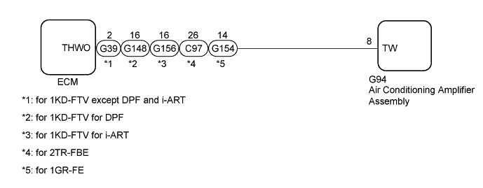
WIRING DIAGRAM
INSPECTION PROCEDURE
Check the vehicle type.
ResultResult
| Proceed to
|
for 1KD-FTV
| A
|
for 2TR-FBE or 1GR-FE
| B
|
| 2.CHECK FOR DTC (ENGINE CONTROL SYSTEM) |
Clear the DTCs.
- for 1KD-FTV (w/ EGR Cooler): HILUX_TGN26 RM000000PDK12RX.html.
- for 1KD-FTV (w/o EGR Cooler): HILUX_TGN26 RM000000PDK12SX.html.
- for 1KD-FTV (for DPF): HILUX_TGN26 RM000000PDK12QX.html.
- for 1KD-FTV (for i-ART): HILUX_TGN26 RM000000PDK12TX.html.
Check the DTCs.
- for 1KD-FTV (w/ EGR Cooler): HILUX_TGN26 RM000000PDK12RX.html.
- for 1KD-FTV (w/o EGR Cooler): HILUX_TGN26 RM000000PDK12SX.html.
- for 1KD-FTV (for DPF): HILUX_TGN26 RM000000PDK12QX.html.
- for 1KD-FTV (for i-ART): HILUX_TGN26 RM000000PDK12TX.html.
ResultResult
| Proceed to
|
DTC (P0115, P0117 or P0118) is not output.
| A
|
DTC (P0115, P0117 or P0118) is output. (for 1KD-FTV [w/ EGR Cooler])
| B
|
DTC (P0115, P0117 or P0118) is output. (for 1KD-FTV [w/o EGR Cooler])
| C
|
DTC (P0115, P0117 or P0118) is output. (for 1KD-FTV [for DPF])
| D
|
DTC (P0115, P0117 or P0118) is output. (for 1KD-FTV [for i-ART])
| E
|
| 3.CHECK HARNESS AND CONNECTOR (AIR CONDITIONING AMPLIFIER - ECM) |
Disconnect the G94 air conditioning amplifier assembly connector.
Disconnect the G39*1, G148*2 or G156*3 ECM connector.
- *1: for 1KD-FTV except DPF and i-ART
- *2: for 1KD-FTV for DPF
- *3: for 1KD-FTV for i-ART
Measure the resistance according to the value(s) in the table below.
- Standard Resistance:
- for 1KD-FTV except DPF and i-ART:
Tester Connection
| Condition
| Specified Condition
|
G94-8 (TW) - G39-2 (THWO)
| Always
| Below 1 Ω
|
G94-8 (TW) - Body ground
| Always
| 10 kΩ or higher
|
- for 1KD-FTV for DPF:
Tester Connection
| Condition
| Specified Condition
|
G94-8 (TW) - G148-16 (THWO)
| Always
| Below 1 Ω
|
G94-8 (TW) - Body ground
| Always
| 10 kΩ or higher
|
- for 1KD-FTV for i-ART:
Tester Connection
| Condition
| Specified Condition
|
G94-8 (TW) - G156-16 (THWO)
| Always
| Below 1 Ω
|
G94-8 (TW) - Body ground
| Always
| 10 kΩ or higher
|
ResultResult
| Proceed to
|
OK (When troubleshooting according to problem symptoms table.)
| A
|
OK (When troubleshooting according to DTC.)
| B
|
NG
| C
|
| |
|
| | REPAIR OR REPLACE HARNESS OR CONNECTOR |
|
|
| 4.CHECK FOR DTC (ENGINE CONTROL SYSTEM) |
Clear the DTCs.
- for 2TR-FBE: HILUX_TGN26 RM000000PDK12LX.html.
- for 1GR-FE: HILUX_TGN26 RM000000PDK12JX.html.
Check the DTCs.
- for 2TR-FBE: HILUX_TGN26 RM000000PDK12LX.html.
- for 1GR-FE: HILUX_TGN26 RM000000PDK12JX.html.
ResultResult
| Proceed to
|
DTC (P0115, P0117 or P0118) is not output.
| A
|
DTC (P0115, P0117 or P0118) is output. (for 2TR-FBE)
| B
|
DTC (P0115, P0117 or P0118) is output. (for 1GR-FE)
| C
|
| 5.CHECK HARNESS AND CONNECTOR (AIR CONDITIONING AMPLIFIER - ECM) |
Disconnect the G94 air conditioning amplifier assembly connector.
Disconnect the C97*1 or G154*2 ECM connector.
- *1: for 2TR-FBE
- *2: for 1GR-FE
Measure the resistance according to the value(s) in the table below.
- Standard Resistance:
- for 2TR-FBE:
Tester Connection
| Condition
| Specified Condition
|
G94-8 (TW) - C97-26 (THWO)
| Always
| Below 1 Ω
|
G94-8 (TW) - Body ground
| Always
| 10 kΩ or higher
|
- for 1GR-FE:
Tester Connection
| Condition
| Specified Condition
|
G94-8 (TW) - G154-14 (THWO)
| Always
| Below 1 Ω
|
G94-8 (TW) - Body ground
| Always
| 10 kΩ or higher
|
ResultResult
| Proceed to
|
OK (When troubleshooting according to problem symptoms table.)
| A
|
OK (When troubleshooting according to DTC.)
| B
|
NG
| C
|
| |
|
| | REPAIR OR REPLACE HARNESS OR CONNECTOR |
|
|