CHECK FOR ANY OTHER DTCS OUTPUT
CHECK ECM (FUEL PRESSURE SENSOR VOLTAGE)
CHECK HARNESS AND CONNECTOR (INJECTOR ASSEMBLY - ECM)
REPLACE INJECTOR ASSEMBLY (RELEVANT CYLINDER)
REPAIR OR REPLACE HARNESS OR CONNECTOR
CONFIRM WHETHER MALFUNCTION HAS BEEN SUCCESSFULLY REPAIRED
DTC P13A1 Fuel Pressure Sensor Circuit Low #1(Sub CPU) |
DTC P13A2 Fuel Pressure Sensor Circuit High #1(Sub CPU) |
DTC P13A3 Fuel Pressure Sensor Circuit Range/Performance #1 |
DTC P13A6 Fuel Pressure Sensor Circuit Low #2(Sub CPU) |
DTC P13A7 Fuel Pressure Sensor Circuit High #2(Sub CPU) |
DTC P13A8 Fuel Pressure Sensor Circuit Range/Performance #2 |
DTC P13AB Fuel Pressure Sensor Circuit Low #3(Sub CPU) |
DTC P13AC Fuel Pressure Sensor Circuit High #3(Sub CPU) |
DTC P13AD Fuel Pressure Sensor Circuit Range/Performance #3 |
DTC P13B1 Fuel Pressure Sensor Circuit Low #4(Sub CPU) |
DTC P13B2 Fuel Pressure Sensor Circuit High #4(Sub CPU) |
DTC P13B3 Fuel Pressure Sensor Circuit Range/Performance #4 |
DTC P13E1 Fuel Pressure Sensor Circuit Low #1(Main CPU) |
DTC P13E2 Fuel Pressure Sensor Circuit High #1(Main CPU) |
DTC P13E6 Fuel Pressure Sensor Circuit Low #4(Main CPU) |
DTC P13E7 Fuel Pressure Sensor Circuit High #4(Main CPU) |
DESCRIPTION
A fuel pressure sensor, which is built into the injector assembly, converts the fuel pressure to an electrical signal which is sent to the ECM. Based on this signal, the ECM controls the fuel supply pump assembly and maintains the fuel pressure in the common rail assembly at the target pressure. A semiconductor is used in the fuel pressure sensor. The semiconductor changes its internal resistance value according to the fuel pressure, and as a result, the output voltage is proportional to the fuel pressure.| DTC Detection Drive Pattern | DTC Detection Condition | Trouble Area |
| Ignition switch ON for 1 second or more | Sub CPU Side: The output voltage of the fuel pressure sensor is 0.55 V or less for 0.5 seconds or more. (1 trip detection logic) |
|
| DTC Detection Drive Pattern | DTC Detection Condition | Trouble Area |
| Ignition switch ON for 1 second or more | Sub CPU Side: The output voltage of the fuel pressure sensor is 4.84 V or higher for 0.5 seconds or more. (1 trip detection logic) |
|
| DTC Detection Drive Pattern | DTC Detection Condition | Trouble Area |
| Ignition switch ON for 8 seconds or more | Main CPU Side: The fuel pressure sensor output voltage of injector #1 and/or #4 is below 0.5 V for 3 seconds or more. (1 trip detection logic) |
|
| DTC Detection Drive Pattern | DTC Detection Condition | Trouble Area |
| Ignition switch ON for 8 seconds or more | Main CPU Side: The fuel pressure sensor output voltage of injector #1 and/or #4 is higher than 4.85 V for 3 seconds or more. (1 trip detection logic) |
|
| DTC Detection Drive Pattern | DTC Detection Condition | Trouble Area |
| After idling for 60 seconds, quickly increase engine speed to 2500 rpm repeatedly for 30 seconds | The output of the fuel pressure sensor differs by 33 MPa or more compared to other cylinders for 0.5 seconds or more. (1 trip detection logic) |
|
| DTC No. | Data List |
| P13A1 P13A2 P13A6 P13A7 P13AB P13AC P13B1 P13B2 |
|
| P13E1 P13E2 P13E6 P13E7 | |
| P13A3 P13A8 P13AD P13B3 |
- HINT:
- Check Fuel Press and compare it to Target Common Rail Pressure in the Data List by entering the following menus: Powertrain / Engine / Data List / Fuel Press, Target Common Rail Pressure. Under stable conditions, the difference between Fuel Press and Target Common Rail Pressure is 5000 kPa or less.
- For more information on the fuel pressure sensor and common rail system, refer to System Description (HILUX_TGN26 RM000000XSN02DX.html).
- If DTC P13A1, P13A2, P13A6, P13A7, P13AB, P13AC, P13B1, P13B2, P13E1, P13E2, P13E6 and/or P13E7 is stored, the following symptom may appear:
- Lack of power due to accelerator restriction performed by fail-safe function
- If DTC P13A1, P13A2, P13A6, P13A7, P13AB, P13AC, P13B1, P13B2, P13E1, P13E2, P13E6 and/or P13E7 is stored, "Fuel Press" always displays -53000 kPa or 255992 kPa.
MONITOR DESCRIPTION
- P13A1, P13A2, P13A6, P13A7, P13AB, P13AC, P13B1, P13B2, P13E1, P13E2, P13E6 and/or P13E7 (Open or short in fuel pressure sensor circuit):
If the fuel pressure sensor output voltage is outside of the standard range due to an open or short in the fuel pressure sensor circuit, DTCs are stored.
If a DTC is stored, the ECM enters fail-safe mode, and engine output is limited only if 2 or more circuits are malfunctioning. The ECM continues operating in fail-safe mode until the ignition switch is turned off.
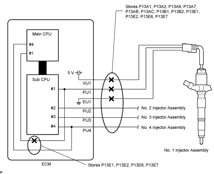
The No. 1 injector assembly and No. 4 injector assembly have separate circuits inside the ECU and a fuel pressure sensor value is input to both the Main CPU and Sub CPU.- HINT:
- When there is an open circuit in EIJ or VIJ, DTC P13E2 and P13A2 are output at the same time.
- If only one of them are output, there may be an open in the internal circuit of the ECM.
WIRING DIAGRAM
Refer to DTC P0201 (HILUX_TGN26 RM00000187V043X_06.html).INSPECTION PROCEDURE
- NOTICE:
- After replacing the ECM, the new ECM needs registration (HILUX_TGN26 RM0000012XK05AX.html) and initialization (HILUX_TGN26 RM000000TIN058X.html).
- HINT:
- Read freeze frame data using the GTS. Freeze frame data records the engine condition when malfunctions are detected. When troubleshooting, freeze frame data can help determine if the vehicle was moving or stationary, if the engine was warmed up or not, and other data from the time the malfunction occurred.
| 1.CHECK FOR ANY OTHER DTCS OUTPUT |
Connect the GTS to the DLC3.
Turn the ignition switch to ON and turn the GTS on.
Enter the following menus: Powertrain / Engine / Trouble Codes.
Read the DTCs.
Result Result Proceed to "Fuel pressure sensor circuit DTC" and "Injector Internal EEPROM Malfunction circuit DTC" are output*1 A Except above B - HINT:
- *: Fuel pressure sensor circuit DTC and Injector Internal EEPROM Malfunction circuit DTC:
Fuel pressure sensor circuit DTC: P13A3, P13A8, P13AD, P13B3.
Injector Internal EEPROM Malfunction circuit DTC: P168A, P168B, P168C, P168D. - When there is an injector internal EEPROM malfunction, fuel pressure sensor circuit range/performance and fuel temperature sensor circuit range/performance DTCs are output at the same time.
For example, when P168A is output, P13A3 and P13C3 are output together.
|
| ||||
| B | |
| 2.CHECK ECM (FUEL PRESSURE SENSOR VOLTAGE) |
Disconnect the fuel pressure sensor connector.
Measure the voltage according to the value(s) in the table below.
Text in Illustration *a Component with harness connected
(ECM)- Standard Voltage:
Tester Connection Switch Condition Specified Condition C166-18 (VIJ1) - C166-6 (EIJ1) Ignition switch ON 4.5 to 5.5 V C166-17 (VIJ2) - C166-5 (EIJ2) Ignition switch ON 4.5 to 5.5 V C166-16 (VIJ3) - C166-4 (EIJ3) Ignition switch ON 4.5 to 5.5 V C166-15 (VIJ4) - C166-3 (EIJ4) Ignition switch ON 4.5 to 5.5 V
 |
|
| ||||
| OK | |
| 3.CHECK HARNESS AND CONNECTOR (INJECTOR ASSEMBLY - ECM) |
Disconnect the injector assembly connector.
Disconnect the ECM connector.
Measure the resistance according to the value(s) in the table below.
- Standard Resistance:
Tester Connection Condition Specified Condition C159-2 (VIJ1) - C166-18 (VIJ1) Always Below 1 Ω C159-4 (PIJ1) - C166-12 (PIJ1) Always Below 1 Ω C159-1 (EIJ1) - C166-6 (EIJ1) Always Below 1 Ω C160-2 (VIJ2) - C166-17 (VIJ2) Always Below 1 Ω C160-4 (PIJ2) - C166-11 (PIJ2) Always Below 1 Ω C160-1 (EIJ2) - C166-5 (EIJ2) Always Below 1 Ω C161-2 (VIJ3) - C166-16 (VIJ3) Always Below 1 Ω C161-4 (PIJ3) - C166-10 (PIJ3) Always Below 1 Ω C161-1 (EIJ3) - C166-4 (EIJ3) Always Below 1 Ω C162-2 (VIJ4) - C166-15 (VIJ4) Always Below 1 Ω C162-4 (PIJ4) - C166-9 (PIJ4) Always Below 1 Ω C162-1 (EIJ4) - C166-3 (EIJ4) Always Below 1 Ω C159-4 (PIJ1) or C166-12 (PIJ1) - Body ground Always 10 kΩ or higher C159-1 (EIJ1) or C166-6 (EIJ1) - Body ground Always 10 kΩ or higher C160-4 (PIJ2) or C166-11 (PIJ2) - Body ground Always 10 kΩ or higher C160-1 (EIJ2) or C166-5 (EIJ2) - Body ground Always 10 kΩ or higher C161-4 (PIJ3) or C166-10 (PIJ3) - Body ground Always 10 kΩ or higher C161-1 (EIJ3) or C166-4 (EIJ3) - Body ground Always 10 kΩ or higher C162-4 (PIJ4) or C166-9 (PIJ4) - Body ground Always 10 kΩ or higher C162-1 (EIJ4) or C166-3 (EIJ4) - Body ground Always 10 kΩ or higher
Reconnect the injector assembly connector.
Reconnect the ECM connector.
|
| ||||
| OK | |
| 4.REPLACE INJECTOR ASSEMBLY (RELEVANT CYLINDER) |
Replace the injector assembly of the cylinder relevant to the DTC (HILUX_TGN26 RM0000044TN00FX.html).
- NOTICE:
- When replacing the injector assembly for a cylinder, always be sure to use a new injection pipe.
- Follow the procedure in the repair manual and temporarily install the injection pipes and nozzle leakage pipe, and then correctly position the injector assemblies. After that, tighten parts according to the torque specifications.
- If the installation procedure is not performed correctly, injector assemblies may become out of position, which may cause the injector assemblies to deteriorate, resulting in malfunctions.
- If an injector assembly deteriorates and malfunctions, other problems such as knocking, rough idle, etc. may occur.
- If an injector assembly becomes out of position, it is possible that the seal between the injector assembly and injection pipe may become incomplete, resulting in a fuel leak.
| NEXT | |
| 5.BLEED AIR FROM FUEL SYSTEM |
Bleed the air from the fuel system (HILUX_TGN26 RM000002SY802GX_01_0002.html).
|
| ||||
| 6.REPLACE ECM |
Replace the ECM (HILUX_TGN26 RM0000013Z001IX.html).
|
| ||||
| 7.REPAIR OR REPLACE HARNESS OR CONNECTOR |
Repair or replace the harness or connector.
| NEXT | |
| 8.CONFIRM WHETHER MALFUNCTION HAS BEEN SUCCESSFULLY REPAIRED |
Connect the GTS to the DLC3.
Clear the DTCs (HILUX_TGN26 RM000000PDK0X4X.html).
- HINT:
- Perform the following when there are DTCs which are not cleared.
- Turn the ignition switch off for 30 seconds or more.
- Turn the ignition switch to ON for 8 seconds or more.
- Enter the following menus: Powertrain / Engine / Trouble Codes / Clear.
- Check that all DTCs have been cleared.
Turn the ignition switch off for 30 seconds or more.
Turn the ignition switch to ON for 8 seconds or more.
Start the engine.
After idling for 60 seconds, increase the engine speed from idling to 2500 rpm repeatedly for 30 seconds.
Enter the following menus: Powertrain / Engine / Trouble Codes.
Confirm that the DTC is not output again.
| NEXT | ||
| ||