Front Stabilizer Bar Installation
INSTALL NO. 1 FRONT STABILIZER BAR BUSHING (for LH Side)
INSTALL NO. 1 FRONT STABILIZER BAR BUSHING (for RH Side)
INSTALL FRONT STABILIZER BAR
INSTALL FRONT SUSPENSION CROSSMEMBER SUB-ASSEMBLY (for TMC Made)
REMOVE FRONT SUSPENSION CROSSMEMBER SUB-ASSEMBLY (except TMC Made)
CONNECT FRONT LOWER SUSPENSION ARM LH
CONNECT FRONT LOWER SUSPENSION ARM RH
INSTALL FRONT STABILIZER LINK ASSEMBLY LH
INSTALL FRONT STABILIZER LINK ASSEMBLY RH
CONNECT TIE ROD END SUB-ASSEMBLY LH
CONNECT TIE ROD END SUB-ASSEMBLY RH
CONNECT NO. 1 STEERING COLUMN HOLE COVER SUB-ASSEMBLY
CONNECT NO. 2 STEERING INTERMEDIATE SHAFT ASSEMBLY
PLACE FRONT WHEELS FACING STRAIGHT AHEAD
INSTALL COLUMN HOLE COVER SILENCER SHEET
INSTALL FRONT WHEELS
INSPECT AND ADJUST FRONT WHEEL ALIGNMENT
Front Stabilizer Bar -- Installation |
| 1. INSTALL NO. 1 FRONT STABILIZER BAR BUSHING (for LH Side) |
Install the No. 1 front stabilizer bar bushing to the front stabilizer bar as shown in the illustration.
- NOTICE:
- Install the No. 1 front stabilizer bar bushing so that the cutout faces the rear of the vehicle.
- Make sure that the amount of deviation of the front stabilizer bar in the horizontal direction is within +/- 5 mm (0.20 in.).
| 2. INSTALL NO. 1 FRONT STABILIZER BAR BUSHING (for RH Side) |
- HINT:
- Perform the same procedure as the LH side.
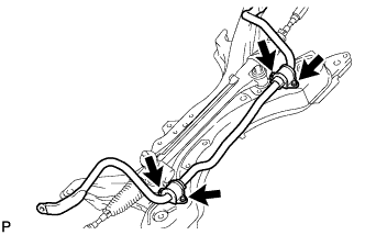
| 3. INSTALL FRONT STABILIZER BAR |
Install the front stabilizer bar and 2 No. 1 front stabilizer brackets to the front suspension crossmember with the 4 bolts.
- Torque:
- TMC Made:
- 19 N*m{194 kgf*cm, 14 ft.*lbf}
- except TMC Made:
- 24 N*m{245 kgf*cm, 18 ft.*lbf}
- NOTICE:
- Check the type of bolt before installing, Look at strength division number of the bolt head.
- 11T: TMC Made
- 10T: except TMC Made
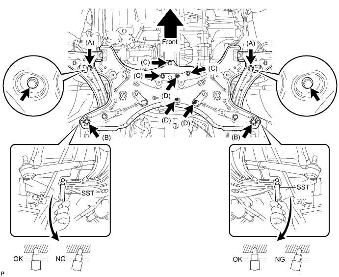
| 4. INSTALL FRONT SUSPENSION CROSSMEMBER SUB-ASSEMBLY (for TMC Made) |
While alternately inserting SST into the guide holes on both sides of the front suspension crossmember RH and LH, tighten 2 bolts (A), 2 bolts (B), 3 bolts (C), and 3 nuts (D) on the RH and LH sides to the respective specified torque in several steps.
- SST
- 09670-00010
- Torque:
- Bolt A:
- 113 N*m{1152 kgf*cm, 83 ft.*lbf}
- Bolt B:
- 157 N*m{1600 kgf*cm, 116 ft.*lbf}
- Bolt C:
- 52 N*m{530 kgf*cm, 38 ft.*lbf}
- Nut D:
- 52 N*m{530 kgf*cm, 38 ft.*lbf}
| 5. REMOVE FRONT SUSPENSION CROSSMEMBER SUB-ASSEMBLY (except TMC Made) |
While alternately inserting SST into the guide holes on both sides of the front suspension crossmember RH and LH, tighten 2 bolts (A), 2 bolts (B), 2 bolts (C), bolt (D) and 3 nuts (E) on the RH and LH sides to the respective specified torque in several steps.
- SST
- 09670-00010
- Torque:
- Bolt A:
- 113 N*m{1152 kgf*cm, 83 ft.*lbf}
- Bolt B:
- 157 N*m{1600 kgf*cm, 116 ft.*lbf}
- Bolt C:
- 52 N*m{530 kgf*cm, 38 ft.*lbf}
- Bolt D:
- 87 N*m{887 kgf*cm, 64 ft.*lbf}
- Nut E:
- 52 N*m{530 kgf*cm, 38 ft.*lbf}
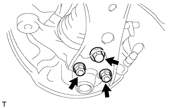
| 6. CONNECT FRONT LOWER SUSPENSION ARM LH |
Install the front lower suspension arm to the lower ball joint with the bolt and 2 nuts.
- Torque:
- 89 N*m{908 kgf*cm, 66 ft.*lbf}
| 7. CONNECT FRONT LOWER SUSPENSION ARM RH |
- HINT:
- Perform the same procedure as the LH side.
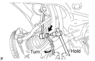
| 8. INSTALL FRONT STABILIZER LINK ASSEMBLY LH |
Install the front stabilizer link assembly LH to the front shock absorber with coil spring with the nut.
- Torque:
- 74 N*m{755 kgf*cm, 55 ft.*lbf}
- HINT:
- If the ball joint turns together with the nut, use a hexagon wrench (6 mm) to hold the stud bolt.
Install the front stabilizer link assembly LH to the front stabilizer bar with the nut.
- Torque:
- 74 N*m{755 kgf*cm, 55 ft.*lbf}
- HINT:
- If the ball joint turns together with the nut, use a hexagon wrench (6 mm) to hold the stud bolt.
| 9. INSTALL FRONT STABILIZER LINK ASSEMBLY RH |
- HINT:
- Perform the same procedure as the LH side.
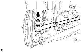
| 10. CONNECT TIE ROD END SUB-ASSEMBLY LH |
Connect the tie rod end sub-assembly LH to the steering knuckle with the nut.
- Torque:
- 49 N*m{500 kgf*cm, 36 ft.*lbf}
- NOTICE:
- Further tighten the nut up to 60° if the holes for the cotter pin are not aligned.
Install a new cotter pin.
| 11. CONNECT TIE ROD END SUB-ASSEMBLY RH |
- HINT:
- Perform the same procedure as the LH side.
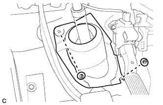
| 12. CONNECT NO. 1 STEERING COLUMN HOLE COVER SUB-ASSEMBLY |
Engage clip B onto the body and install the No. 1 steering column hole cover sub-assembly onto the body with clips A.
- NOTICE:
- Make sure that the lip of the No. 1 steering column hole cover sub-assembly is not damaged.
| 13. CONNECT NO. 2 STEERING INTERMEDIATE SHAFT ASSEMBLY |
Align the matchmarks on the No. 2 steering intermediate shaft assembly and the steering intermediate shaft assembly.
Install the bolt.
- Torque:
- 35 N*m{360 kgf*cm, 26 ft.*lbf}
| 14. PLACE FRONT WHEELS FACING STRAIGHT AHEAD |
| 15. INSTALL COLUMN HOLE COVER SILENCER SHEET |
Install the column hole cover silencer sheet with the 2 clips.
Install the floor carpet.
- Torque:
- 103 N*m{1050 kgf*cm, 76 ft.*lbf}
| 17. INSPECT AND ADJUST FRONT WHEEL ALIGNMENT |
- HINT:
- Inspect and adjust front wheel alignment (COROLLA_ZRE142 RM000001Y3B042X.html).