INSTALL DRIVE PLATE AND RING GEAR SUB-ASSEMBLY (for Automatic Transaxle)
INSPECT AND ADJUST CLUTCH COVER ASSEMBLY (for Manual Transaxle)
INSTALL AUTOMATIC TRANSAXLE ASSEMBLY (for Automatic Transaxle)
Rear Crankshaft Oil Seal -- Installation |
| 1. INSTALL REAR ENGINE OIL SEAL |
Apply MP grease to the lip of a new oil seal.
- NOTICE:
- Keep the lip free from foreign matter.
Using SST and a hammer, tap in the oil seal until its surface is flush with the rear oil seal retainer edge.
- SST
- 09223-15030
09950-70010(09951-07100)
- NOTICE:
- Wipe any extra grease off the crankshaft.
- Do not tap the oil seal at an angle.
 |
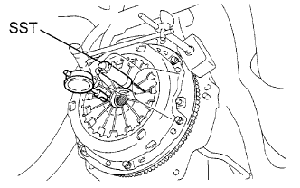
| 2. INSTALL FLYWHEEL SUB-ASSEMBLY (for Manual Transaxle) |
Using SST, hold the crankshaft.
- SST
- 09213-58014(91551-80840)
09330-00021
- NOTICE:
- Check the SST installation positions when installing them to prevent the SST fixing bolts from coming into contact with the timing chain cover sub-assembly.
 |
Apply adhesive to 2 or 3 threads of the bolt ends.
- Adhesive:
- Toyota Genuine Adhesive 1324, Three Bond 1324 or equivalent
 |
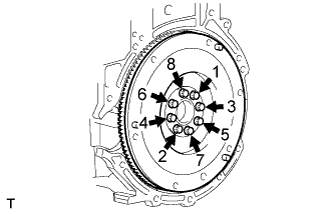
Using several steps, uniformly install and tighten the 8 bolts in the sequence shown in the illustration.
- Torque:
- 49 N*m{500 kgf*cm, 36 ft.*lbf}
 |
Mark the top of the bolts with paint.
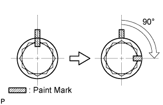 |
Further tighten the 8 bolts an additional 90° in the same sequence.
Check that the paint marks are now at a 90° angle to the top.
Check that the crankshaft turns smoothly.
| 3. INSTALL DRIVE PLATE AND RING GEAR SUB-ASSEMBLY (for Automatic Transaxle) |
Using SST, hold the crankshaft.
- SST
- 09213-58014(91551-80840)
09330-00021
- NOTICE:
- Check the SST installation positions when installing them to prevent the SST fixing bolts from coming into contact with the timing chain cover sub-assembly.
|
Clean the bolts and the bolt holes.
Apply a few drops of adhesive to 2 or 3 threads of the 8 bolts tip.
- Adhesive:
- Toyota Genuine Adhesive 1324, Three Bond 1324 or equivalent
|
Install the front spacer, drive plate and rear spacer with the 8 bolts. uniformly tighten the 8 bolts in the sequence shown in the illustration.
- Torque:
- 88 N*m{897 kgf*cm, 65 ft.*lbf}
 |
| 4. INSTALL CLUTCH DISC ASSEMBLY (for Manual Transaxle) |
Insert SST into the clutch disc assembly, then insert them both into the flywheel sub-assembly.
- SST
- 09301-00110
- NOTICE:
- Insert the clutch disc assembly in the correct direction.
 |
| 5. INSTALL CLUTCH COVER ASSEMBLY (for Manual Transaxle) |
Align the matchmark on the clutch cover assembly with the one on the flywheel sub-assembly.
 |
Following the procedure shown in the illustration, tighten the 6 bolts in order, starting with the bolt located near the knock pin at the top.
- Torque:
- 19 N*m{195 kgf*cm, 14 ft.*lbf}
- HINT:
- Following the order in the illustration, tighten the bolts evenly one at a time.
- Move SST up and down, right and left lightly after checking that the disc is in the center, and tighten the bolts.
- SST
- 09301-00110
| 6. INSPECT AND ADJUST CLUTCH COVER ASSEMBLY (for Manual Transaxle) |
Using a dial indicator with a roller instrument, check the diaphragm spring tip alignment.
- Maximum non-alignment:
- 0.9 mm (0.0354 in.)
 |
If the alignment is not as specified, adjust the diaphragm spring tip alignment using SST.
- SST
- 09333-00013
| 7. INSTALL MANUAL TRANSAXLE ASSEMBLY (for Manual Transaxle) |
- HINT:
- COROLLA_ZRE142 RM000001B3U06SX.html for C59.
| 8. INSTALL AUTOMATIC TRANSAXLE ASSEMBLY (for Automatic Transaxle) |
- HINT:
- COROLLA_ZRE142 RM00000192B050X.html for U341E.
| 9. INSTALL ENGINE ASSEMBLY WITH TRANSAXLE |
- HINT: